CONTROL PANEL OPERATING PROCEDURES
13
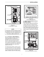
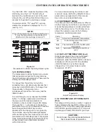
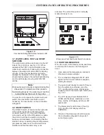
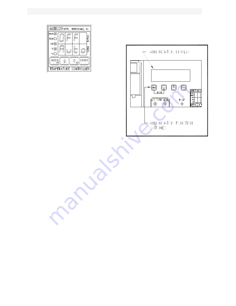
Figure 3.7
Auto/Manual Display with Manual On
3.4 THE SECONDARY MENU
The secondary menu is primarily related to
temperature control. It is necessary to access
this menu when setting PID values or changing
the unit mode of operation. All the parameters
accessible in the primary menu are also
accessible in the secondary menu.
To access the secondary menu, press the
×
arrow key and ENTER simultaneously. To scroll
through the menu press the INDEX button. For a
complete explanation of the secondary menu
parameters see Appendix A of this manual.
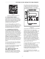
3.5 THE ANNUNCIATOR CIRCUIT
The annunciator consists of the annnciator
circuit board, the front panel LCD display, and 4
function switches, (see Fig. 3.8 for the display
and function switch locations and see Appendix I
for the circuit board locations). The annunciator
circuit board is the interface between the LCD
display and the combustion safeguard system. It
monitors the unit during every phase of
operation and prompts the LCD display with
start sequence and fault messages. The function
switches are used to reset the annunciator and
gain access to the annunciator’s three function
displays.
The annunciator circuit board and LCD display
are not an integral part of the start sequence or
combustion safeguard system.
The annunciator start sequence messages, fault
messages, function switches and function
displays are explained below.
3.5.1 ANNUNCIATOR FUNCTION
SWITCHES and DISPLAYS
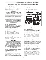
The Annunciator has three function displays
available to the operator. These are the MAIN,
the CYCLES, and the SET DATE displays.
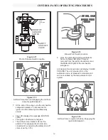
These displays are accessed using the four
membrane switches located directly under the
LCD display on the front of the control panel.
They are labeled CLEAR,
×
,
Ø
, and AUX.
Figure 3.8
Annunciator Function Switches and LCD Display
The MAIN display is used during normal
operation of the unit. In the MAIN display, start
sequence and fault messages can viewed. To
return to the MAIN display from any other
display, simultaneously press CLEAR and the
×
arrow key. To reset the MAIN display after a
fault has occurred press the CLEAR button.
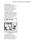
The CYCLES display indicates the date and
time, and the number of cycles the unit has
started. When in the CYCLES display only the
number of cycles can be reset. To reset the
number of cycles to 0, simultaneously press the
×
, and
Ø
arrow keys and hold them for
approximately four seconds.
In the SET DATE display, both the time and date
are displayed and can be changed.
To access the SET DATE display, press the
CLEAR button while in the CYCLES display.
Continue pressing the CLEAR button to move
through the SET DATE display fields. Use the
×
Ø
arrow keys to set the date and time.
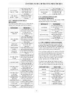
The following table shows the messages
displayed after accessing the CYCLES and SET
DATE displays.
Summary of Contents for AERCO KC Series
Page 51: ...TROUBLESHOOTING 41...
Page 65: ...APPENDIX C ix...
Page 72: ...APPENDIX F xvi...
Page 74: ...APPENDIX F xviii...
Page 76: ...APPENDIX G xx...
Page 77: ...APPENDIX G xxi...
Page 78: ...APPENDIX H xxii...
Page 79: ...APPENDIX H xxiii...
Page 80: ...APPENDIX H xxiv...

