background image

INSTALLATION


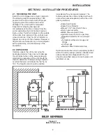
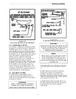
Figure 2.5b 

Pressure/Temperature Gauge Installation


2.3.5 CONDENSATE PIPING  

The KC Boiler is designed to condense and the 
installation must have provisions for drainage to 
a suitable waste. A 1-3/4” inch O.D. silicone 
hose, supplied with the unit, directs condensate 
from the exhaust manifold to a stainless steel 
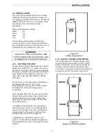
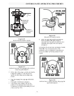
condensate cup. The condensate cup is shipped 
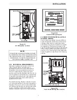
loose and should be installed inside the unit 
directly under the manifold’s condensate 
drainage hole (see FIG. 2.6). A 5/8-inch O.D. 
flexible polypropylene tubing (or suitable 
equivalent) can be used to carry the condensate 
by gravity to a nearby floor drain. If a floor drain 
is not available, a condensate pump can be 
used to remove the condensate to drain.  The 
maximum condensate flow rate is 5 GPH.  The 
condensate cup and line must be removable for 
routine maintenance. Do not hard pipe. 


2.4.  GAS SUPPLY PIPING 

The AERCO


Gas Fired Equipment Gas 

Components and Supply Design Guide (GF-
1030) must be consulted before any gas piping 
is designed or started. 


WARNING! 

DO NOT USE MATCHES, CANDLES, 

FLAMES OR OTHER SOURCES OF 

IGNITION TO CHECK FOR GAS LEAKS

.  


Figure 2.6 

Condensate Drain System Location 

CAUTION! 

Soaps used for gas pipe leak testing can be 

corrosive to metals. Piping must be rinsed 

thoroughly with clean water after leak 

checks have been completed

.


NOTE:  

All gas piping must be arranged so that it 

does not interfere with removal of any 

cover, inhibit service or maintenance, or 

prevent access between the Unit and walls, 

or another unit. 

 
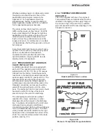
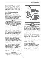
The location of the 1-1/4" inlet gas connection is 
on the right side of the unit as shown in Figure 
2.7.  
 
All pipe should be de-burred and internally 
cleared of any scale or iron chips before 
installation. No flexible connectors or non-
approved gas fittings should be installed. Piping 
should be supported from floor or walls only and 
must not be secured to the unit. 
 
A suitable piping compound, approved for use 
with gas, should be used sparingly. Any excess 
must be wiped off to prevent clogging of 
components.

Summary of Contents for AERCO KC Series

Page 1: ...ies Gas Fired Boiler USER MANUAL Applicable for Serial Numbers G 01 026 to G 09 XXX KC Series Gas Fired Boiler System Semi Instantaneous Condensing Forced Draft Natural Gas and Propane Fired Hot Water...

Page 2: ...ration and maintenance manual is subject to change without notice from Aerco International Inc Aerco makes no warranty of any kind with respect to this material including but not limited to implied wa...

Page 3: ...he Secondary Menu 3 5 The Annunciator Circuit 3 6 The Combustion Safeguard 3 7 Water Level Test and Reset 3 8 On Off Switch 3 9 Starting Sequence 3 10 After Flame 3 11 Flame Test Jacks 3 12 Start Stop...

Page 4: ...tor 7 4 Combustion Calibration 7 5 Safety Device Testing 7 6 Manifold and Exhaust Tubes Section 8 TROUBLESHOOTING 38 8 1 Gas Pressure Fault 8 2 Exhaust Temperature Fault 8 3 Water Level Fault 8 4 Wate...

Page 5: ...um space requirements Venting capabilities offer maximum flexibility and allow installation without normal restrictions The advanced electronics of each boiler module offer selectable modes of operati...

Page 6: ...THE GAS SUPPLY AND THE ELECTRICAL POWER SUPPLY TO THE UNIT WARNING FLUIDS UNDER PRESSURE MAY CAUSE INJURY TO PERSONNEL OR DAMAGE TO EQUIPMENT WHEN RELEASED BE SURE TO SHUT OFF ALL INCOMING AND OUTGOI...

Page 7: ...ing the packaging material Take care not to damage the unit jacket when cutting away packaging materials An inspection of the unit should be made to determine if damage during shipment occurred that w...

Page 8: ...1000 is U L approved for installation on combustible flooring A 4 to 6 high housekeeping concrete pad is recommended and allows for sufficient drainage of the condensate It is suggested that units be...

Page 9: ...actory Install the pressure relief valve in the tapping provided opposite the system supply connection see figure 2 4 The pressure relief valve should be piped in the vertical position using the fitti...

Page 10: ...t Gas Components and Supply Design Guide GF 1030 must be consulted before any gas piping is designed or started WARNING DO NOT USE MATCHES CANDLES FLAMES OR OTHER SOURCES OF IGNITION TO CHECK FOR GAS...

Page 11: ...hould have no more than 1 droop from minimum to full fire The supply gas regulator must also be rated to handle the maximum incoming gas pressure to it When the gas supply pressure will not exceed 14...

Page 12: ...n the side of the box in such a manner that it does not interfere with the removal of any sheet metal covers A flexible electrical connection may be utilized to allow the covers to be removed easily F...

Page 13: ...oper location and wiring instructions 2 6 4 4 to 20 ma REMOTE SETPOINT MODE The KC1000 can be controlled with a 4 20 ma signal from a Building Management System or an external controller The supplied...

Page 14: ...OUTSIDE THE BUILDING Air supplied from outside the building must be provided through two permanent openings For each unit these two openings must have a free area of not less than one square inch for...

Page 15: ...PID programmable controller that utilizes feed forward and feedback information to accurately maintain a desired set point It is the primary source for programming and viewing operating parameter set...

Page 16: ...ter without entering the new value will result in that parameters value defaulting back to the original value Detailed descriptions and instructions for accessing each menu parameter are listed within...

Page 17: ...etpoint Display NOTE Changing the setpoint will only be recognized when the unit is in the automatic mode 3 3 4 AUTOMATIC MANUAL Auto When set to automatic mode the controller is receiving and process...

Page 18: ...system The annunciator start sequence messages fault messages function switches and function displays are explained below 3 5 1 ANNUNCIATOR FUNCTION SWITCHES and DISPLAYS The Annunciator has three fu...

Page 19: ...ressure switch opened after flame was proven LOCKOUT RUN FLAME Flame signal was lost after flame was proven LOCKOUT RUN The combustion safeguard is locked out HI EXHAUST TEMP The exhaust gas temperatu...

Page 20: ...is part of the start string and must be in the ON position to enable the unit to fire When the switch is in the ON position and illuminated it is indicating that the start limit string consisting of...

Page 21: ...ngages the air fuel valve closed switch energizing the safety shut off valve see Fig 3 14 Figure 3 13 Blower Proof Switch Location 8 Once the combustion safeguard detects flame its flame LED lights Po...

Page 22: ...combustion safeguard has two test jacks marked and for flame monitoring see Fig 3 15 To access the test jacks remove the combustion safeguard cover by turning the center screw counterclockwise A stand...

Page 23: ...R PROPERTY DAMAGE THIS IS NOT COVERED BY WARRANTY CAUTION All installation procedures in Section 2 must be completed before attempting to start the unit 4 2 TOOLS AND INSTRUMENTATION FOR COMBUSTION CA...

Page 24: ...asket from the regulator cap onto the regulator adjustment tool 3 Prior to Installing the tools on the regulator pull up the tool s screwdriver blade Then thread the tool into the regulator 4 Engage t...

Page 25: ...ssure will void the warranty 10 Once 8 5 W C or 8 9 W C is set at the 100 level change the firing rate Pct to 30 Insert the combustion analyzer probe into the stack NOTE Always go to a percentage of f...

Page 26: ...Change the firing rate to 100 After the combustion analyzer has settled compare the measured oxygen level with the levels in Table 3 22 If the measured oxygen reading is below the oxygen range in Tab...

Page 27: ...eter 5 This reading should remain a constant 3 8 to 4 W C throughout the operating range 6 If the pressure drop is not within this range remove the cap from the air pressure regulator 7 Using a flat b...

Page 28: ...ure limit switch is a manual reset device and is not adjustable It will shut the unit off if the water temperature reaches 240 o F DO NOT attempt to adjust its set point To adjust the lower over tempe...

Page 29: ...temperature of 70 degrees then at 69 degrees outside temperature the supply header temperature will increase by 1 6 degrees to 71 6 degrees 5 1 3 OUTDOOR AIR SENSOR INSTALLATION When mounting the Out...

Page 30: ...485 signal is in turn sent to the temperature controller For the temperature controller to recognize a signal from an external source the following functions must be correctly set MENU FUNCTION SETTI...

Page 31: ...rce end of the end must be left floating and not connected When driving multiple units each unit s wiring must conform to the above 5 4 2 4 to 20 MA DIRECT DRIVE STARTUP Since this mode of operation i...

Page 32: ...d to cover the space heating load on the design day However one or more of the units are used to heat domestic water while the remaining units take care of the heating load The units used for the dome...

Page 33: ...es to BMS mode the firing rate is controlled by the AERCO BMS Model 168 There are no setup requirements in this mode However when the unit is in BMS mode and it is desired to run the unit in manual mo...

Page 34: ...low the low gas pressure switch See Fig 6 1 3 Open the gas supply to the unit and reset the low gas switch 4 Start the unit 5 Slowly close the manual gas supply valve while monitoring the gas pressure...

Page 35: ...minated and the unit should not start 4 Reset the temperature limit switch setting to its prior setting 5 The unit should start once the temperature limit switch setting is above the actual outlet wat...

Page 36: ...7 PURGE INTERLOCKS FAULT TEST 1 Turn the ON OFF switch to the OFF position 2 Loosen the two setscrews that attach the safety shut off valve actuator to the valve body See Fig 6 5 3 Lift the SSOV actua...

Page 37: ...er from the unit 14 Reconnect wire 60 to the air fuel valve open position switch 15 Disconnect wire 62 from the ignition position switch This is the switch closest to the burner of the unit See Fig 6...

Page 38: ...itor may also be gained by removing the unit s right side panel 3 Disconnect the ignitor cable from the ignitor contactor and unscrew the ignitor contactor from the burner shell 4 Insert the ignitor r...

Page 39: ...scheduled basis Test schedules must conform to local jurisdictions The results of the tests should be recorded in a log book See Section 6 Safety Device Testing Procedures 7 6 MANIFOLD AND EXHAUST TUB...

Page 40: ...8 hex nuts supporting the burner See Fig 7 3 Figure 7 3 Burner Disassembly Diagram 11 Lower the burner while sliding the air hose off the air fuel valve Remove the burner through the rear of the unit...

Page 41: ...or socket remove the 3 bolts and fender washers securing the insulation to the exhaust manifold 21 Loosen the three 1 1 16 nuts that hold the manifold Remove the two side nuts DO NOT REMOVE THE FRONT...

Page 42: ...1 Follow steps 1 through 5 under Section 7 6 2 Using a wrench loosen the two compression fittings holding the 1 4 feedback tube between the burner and air regulator and remove the feedback tube See F...

Page 43: ...tpoint is the desired outlet water temperature that is to be maintained by the boiler when operating in automatic mode When set to automatic mode the temperature controller receives and processes inpu...

Page 44: ...the unit is enabled This parameter is displayed only when OSAT is on This is Low Limit Temperature alarm This will put the temperature controller into alarm if the outlet water temperature goes below...

Page 45: ...the unit This displays the address for the controller It is used for external communication with a computer This changes the local remote status of the controller In local mode all external computer w...

Page 46: ...emperature will increase with each degree change in outside air temperature This menu item turns the outside air enable disable feature on or off When ON an outside air temperature can be chosen to en...

Page 47: ...sted with the and Press ENTER to accept changes This is the derivative rate in 1 sec This adjusts response time to temperature changes at the outlet of the unit This displays the address for the contr...

Page 48: ...be obtained proceed to step 8 4 If static pressure is already 10 to 14 W C or has been readjusted start the unit It may be necessary to depress the reset button on units having manual reset gas switc...

Page 49: ...is higher than 14 W C it may be necessary to replace the gas supply regulator with a lock up style Consult your local AERCO representative for more information 8 2 3 HIGH GAS PRESSURE SWITCH 1 If stat...

Page 50: ...ng 8 3 1 Water Level Probe 8 3 2 Wiring Connections 8 3 3 Water level Circuit Recommended Troubleshooting Equipment x Digital Volt Ohmmeter 8 31 WATER LEVEL PROBE 1 Disconnect the electric power to th...

Page 51: ...TROUBLESHOOTING 41...

Page 52: ...ures can vary and may be higher than the system design temperature Check the actual outlet water temperature of the unit and ensure that the lower temperature switch is 20 o F or more above the actual...

Page 53: ...FIRING 1 Install a DC voltmeter in the flame test jacks located on the front of the combustion safeguard and start the unit 2 Once flame is established a steady reading of approximately 5VDC should b...

Page 54: ...the safety shut off valve actuator 13 If 120VAC is not observed on the AC voltmeter disconnect AC power to the unit 14 Disconnect the 9 pin connector from the control panel and remove the cover from t...

Page 55: ...e the ignition transformer cover plate 12 Referring to system schematic 161413 in Appendix H locate wires 12 and 29 13 Connect an AC voltmeter across wires 12 and 29 14 Reconnect AC power to the unit...

Page 56: ...art the unit 15 If the flame fault still persists contact you re your local AERCO representative safeguard 8 5 8 RESIDUAL FLAME Once the KC1000 has stopped firing it continues to monitor the flame cir...

Page 57: ...it frame 6 Reconnect AC power to the unit 7 Start the unit 8 The AC voltmeter should measure 120VAC 9 If 120VAC is not measured proceed to section 8 6 5 10 If 120VAC is measured check the blower capac...

Page 58: ...tart the unit 2 If the blower starts and the message SYSTEM FAULT PURGE INTERLOCKS is displayed proceed to section 8 7 4 3 If the blower does not start and the message SYSTEM FAULT LOW AIR PRESSURE is...

Page 59: ...the Annunciator displays the message PURGE INTLK OPEN and the air fuel valve does not rotate proceed to section 8 7 7 4 If the air fuel valve rotates to its full open position and engages the air fue...

Page 60: ...ring to system schematic 161413 in Appendix H locate wires 59 and 60 Remove wires 59 and 60 from the air fuel valve open proving switch noting their location The air fuel valve open proving switch is...

Page 61: ...remains at 15 volts r 2 volts during PURGE or remains at 3 volts during ignition replace the relay board 19 If the DC voltage is at 0 volts replace the temperature controller 8 8 8 AIR FUEL VALVE IGNI...

Page 62: ...to SECONDARY MENU Press ENTER and the arrow key The display will indicate x SECONDARY MENU to PRIMARY MENU Press INDEX and the arrow key The display will indicate NOTE When in the Secondary menu the...

Page 63: ...menu press the INDEX key and arrow key OR while in secondary menu press and hold ENTER and for 5 seconds The display will indicate x SECURE MENU to the SECONDARY MENU Pressing either INDEX and arrow...

Page 64: ...reverse simultaneously press INDEX and the arrow key To return to the first menu item of the SECONDARY menu from any other SECONDARY menu item without scrolling simultaneously press the INDEX and the...

Page 65: ...APPENDIX C ix...

Page 66: ...193 206 20F 92 106 120 134 148 162 176 190 204 218 Header Temperature for a Building Reference Temperature of 60F RESET RATIO Air Temp 0 6 0 8 1 0 1 2 1 4 1 6 1 8 2 0 2 2 2 4 60F 60 60 60 60 60 60 60...

Page 67: ...3 129 145 161 177 193 209 20 116 133 150 167 201 218 Header Temperature for a Building Reference Temperature of 70F RESET RATIO Air Temp 0 6 0 8 1 0 1 2 1 4 1 6 1 8 2 0 2 2 2 4 70F 70 70 70 70 70 70 7...

Page 68: ...135 150 165 180 195 210 5F 123 139 155 171 187 203 219 10F 126 143 160 177 194 211 15F 129 147 165 183 201 219 Header Temperature for a Building Reference Temperature of 80F RESET RATIO Air Temp 0 6...

Page 69: ...22 126 130 134 138 65F 105 110 115 120 125 130 135 140 145 150 60F 108 114 120 126 132 138 144 150 156 162 55F 111 118 125 132 139 146 153 160 167 174 50F 114 122 130 138 146 154 162 170 178 186 45F 1...

Page 70: ...T HIGH LIMIT TEMPERATURE 220 pb1 PROPORTIONAL GAIN 70 int INTEGRAL 1 drt DERIVATIVE 0 off addr ADDRESS 32 lore LOCAL REMOTE MODE LOC SECURE secr SECURITY LEVEL 3 func MODE OF OPERATION CONT gain GAIN...

Page 71: ...RE OFF OAt OUTSIDE AIR TEMP 0 LLt LOW LIMIT TEMPERATURE 40 HLt HIGH LIMIT TEMPERATURE 220 Pb1 PROPORTIONAL GAIN 70 Int INTEGRAL 1 drt DERIVATIVE 0 off Addr ADDRESS 32 LOrE LOCAL REMOTE LOC SECURE MENU...

Page 72: ...APPENDIX F xvi...

Page 73: ...5 6 8 1 78 6 7 6 35 6685 9 66 20 867 21 0 5 0 7 5 6 2 216758 7 21 7 1 5 6 1 67 1 5 6 6 6 35 66 36 0 25 1 0 080 7 03 r 7 67 35 66 36 60 39 2 6 7 21 9 67 03 02 67 6 5 6 6 5 2 5 0 16 21 5 1 3 127 6 5 1...

Page 74: ...APPENDIX F xviii...

Page 75: ...5 5 6 75 1 3 5 1 7 176 6 33 7 6 1257 9 1 17 51 7 21 1 5 2 7 5 281 5 72 5 8 9 9 66 137 6 5 8 725 3 1 3 1 7 6 3523 1 5 6629 3 1 1250 23 1 9 17 9 9 3 1 3 9 17 72 70263 5 3 5 16 1 3 6629 78 725 3 1 127 6...

Page 76: ...APPENDIX G xx...

Page 77: ...APPENDIX G xxi...

Page 78: ...APPENDIX H xxii...

Page 79: ...APPENDIX H xxiii...

Page 80: ...APPENDIX H xxiv...

Page 81: ...123437 6 32 X 5 8 LG PAN HEAD MACH SCREW 8 123389 LINE FILTER 7 123436 FAN 6 123393 TERMINAL BLOCK 5 123388 TRANSFORMER 4 123399 VALVE INTERFACE BOARD 3 123747 HONEYWELL FLAME RECIFICATION AMPLIFIER 1...

Page 82: ...123280 B_ TEMPERATURE CONTROLLER NEED STYLE NUMBER 17 123803 SOLID STATE TIMER ARTISAN CORP 123469 FOR SSAC INC 16 123438 CIRCUIT BREAKER 15 123391 RELAY BOARD 14 123390 STATUS ANNUNCIATOR ITEM PART N...

Reviews: