TROUBLESHOOTING
46
29. Reconnect AC power to the unit and start
the unit.
30. If the flame fault still persists, replace the
combustion safeguard.
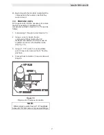
8.5.7 FLAME DETECTOR VOLTAGE
1. Disconnect AC power to the unit.
2. Remove the flame detector lead wire from
the flame detector.
3. Connect an AC voltmeter from the flame
detector lead wire to the frame of the unit.
WARNING !
A SHOCK POTENTIAL EXISTS. THE
FLAME DETECTOR LEAD WIRE HAS A
POTENTIAL OF 345 VAC.
4. Reconnect AC power to the unit.
5. An AC voltage reading of approximately 345
VAC should be observed.
6. If 345 VAC is observed, proceed to Section
8.5.2, Step 8.
7. If 345 VAC is not observed, disconnect AC
power to the unit.
8. Disconnect the 9 pin connector from the
control panel.
9. Referring to system schematic 161413 in
Appendix H, locate wire #9.
10. Check wire #9 for continuity.
11. Check the flame detector end of wire #9 for
loose connections. Inspect the pins in the 9
pin connector for proper insertion and signs
of wear.
12. Repair if necessary.
13. If wire #9 has continuity and all connections
are okay or a repair was performed,
reconnect the flame detector lead to the
flame detector. Reconnect the 9 pin
connector to the control panel.
14. Reconnect AC power to the unit and start
the unit.
15. If the flame fault still persists, contact you’re
your local AERCO representative safeguard.
8.5.8 RESIDUAL FLAME
Once the KC1000 has stopped firing, it
continues to monitor the flame circuit. If a
residual flame exists, the unit will indicate a
LOCKOUT fault. The source of a residual flame
is typically a leaking safety shut-off valve. To
check for a leaking safety shut-off valve proceed
as follows:
1. Shut the unit off by switching the ON-OFF
switch to the Off position
2. Locate the leak detection valve, between the
safety shut-off valve and the differential
pressure regulator.
3. Close the valve and remove a set screw
from its 1/8” leak detection port.
4. Install an 8” or 16.5” manometer.
5. Monitor the manometer for signs of an
increase in gas pressure.
6. If there is an increase in gas pressure,
replace the gas train.
8.6 AIR PRESSURE FAULT
A LOCKOUT RUN AIR FLOW indicates that the
air pressure, while firing, was too low for
operation. Oscillations or rumbling of the unit is
also a common cause this fault.
8.6.1 Determining the Cause of the Fault
8.6.2 Oscillations
8.6.3 Blower
8.6.4 Blower Proof Switch
8.6.5 Solid State Relay
Recommended Troubleshooting Equipment
AC Voltmeter
Ohmmeter
8.6.1 DETERMINING THE CAUSE OF
THE FAULT
1. Clear the Annunciator and start the unit.
2. If the unit does not fault after proving flame,
proceed to Section 8.6.2.
3. If the blower does not start
,
proceed to
Section 8.6.3.
Summary of Contents for AERCO KC Series
Page 51: ...TROUBLESHOOTING 41...
Page 65: ...APPENDIX C ix...
Page 72: ...APPENDIX F xvi...
Page 74: ...APPENDIX F xviii...
Page 76: ...APPENDIX G xx...
Page 77: ...APPENDIX G xxi...
Page 78: ...APPENDIX H xxii...
Page 79: ...APPENDIX H xxiii...
Page 80: ...APPENDIX H xxiv...

