Doc. P/N:
WSP-009-008
Version: V1.3
Issue Date:
April 2014
6
2.2
Info Panel
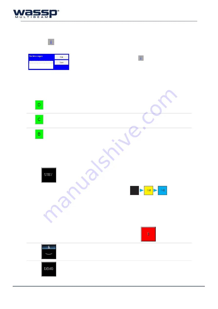
Clicking the
button will reveal the information panel. This panel displays error messages and
information important for the user to know.
Hide
: Hides the information panel. Click the
button again to expand.
Save
: Saves the text in the information panel to file.
2.3
Device Connection Indicators
At the top of the Main Menu are three device connection indicators. The indicators are RED when the
WASSP program is unable to read or detect the device, and GREEN when devices are connected and/
or readable.
►
Dongle
This is the user dongle supplied with your system. This should always be plugged into
your WASSP Processor.
►
Navionics Chart
If you have connected a Navionics chart to use with your WASSP system, this indicator
will be green (see page 62 of the Installation Manual for further information).
►
BTxR (Transceiver)
When the BTxR is ON and connected, this indicator will be green.
2.4
Mode Button
This button is used to control the BTxR, and has four modes:
Standby Mode
The MODE button is BLACK during start up. The button
turns YELLOW for about 3 seconds while the BTxR self-
calibrates and then turns BLUE, indicating the BTxR has
just calibrated and is ready to go.
Start up
Transition
(Self Calibration)
After 3 sec
Cal
Cal
Cal
A RED counting button indicates a communications
failure. This means that a ping was requested but no data
was received. A new ping is sent at least every 5 seconds.
A communications failure can happen if the BTxR power
is interrupted.
Transmit Mode
During transmission, the button animates with each
pulse that the BTxR transmits.
Demo Mode
A BLACK button with DEMO displayed indicates the
system started without a valid dongle.
In this mode, only Replay Files can be viewed.


