background image

Accessories

E 2200, E 3000ES

76                                       

wc_tx001668gb.fm

5.7

Mounting the Auxiliary Pump Panel

Requirments

„

Machine shut down

„

Power disconnected

„

Auxiliary Pump Panel

Background

The Wacker Neuson Auxiliary Pump Panel (APP) is an electrical device that 
communicates with the main machine’s systems to provide protection for any 
additional Pump Packs that are connected to the machine. If the machine 
experiences a low level fault condition, the APP will cut off power to the external 
components. This power cut-off protects the pumps from damage.
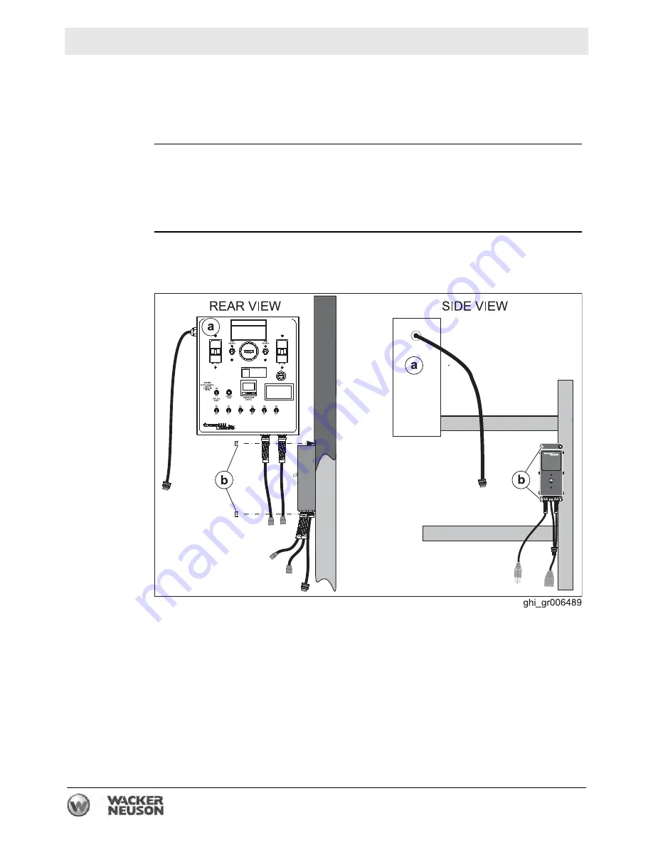
Guidelines

Follow the guidelines below when mounting the APP. Refer to the diagram below.

„

Install the APP inside the machine, near the main control panel 

(a)

.

„

Install APP using included hardware 

(b)

.


Summary of Contents for E 2200

Page 1: ...0192779 001 1210 0 1 9 2 7 7 9 Operator s Manual Hydronic Surface Heater E 2200 E 3000ES...

Page 2: ...distribution not authorized by Wacker Neuson Corporation represents an infringement of valid copyrights Violators will be prosecuted Trademarks All trademarks referenced in this manual are the propert...

Page 3: ...he information contained in this manual is based on machines manufactured up until the time of publication Wacker Neuson Corporation reserves the right to change any portion of this information withou...

Page 4: ...Foreword 4 wc_tx001665gb fm...

Page 5: ...27 3 2 Preparing the Machine for Transport on a Truck or Trailer 28 3 3 Before Towing Checklist 29 4 Operation 30 4 1 Control Component Locations 30 4 2 Control Component Descriptions 31 4 3 Control P...

Page 6: ...Combining the Machine with Two HHS and Two DPP E 2200 only 74 5 7 Mounting the Auxiliary Pump Panel 76 6 Burner Setup 77 6 1 Adjusting the Burner Electrodes 80 6 2 Replacing the Burner Nozzle 83 6 3 S...

Page 7: ...nical Data 110 9 1 E 2200 110 9 2 E 3000ES 111 9 3 Trailer 112 9 4 Dimensions 113 MSDS Dowfrost HD 50 114 Fuji Temperature Controller 121 10 Schematics 124 10 1 Electrical Schematic 124 10 2 Electrica...

Page 8: ...8 wc_bo0192779en_001TOC fm Table of Contents E 2200 E 3000ES...

Page 9: ...al personal hazards f Obey all safety messages that follow this symbol DANGER DANGER indicates a hazardous situation which if not avoided will result in death or serious injury f To avoid death or ser...

Page 10: ...or seriously injure the operator or other persons in the area Machine damage caused by misuse is not covered under warranty The following are some examples of misuse Using the machine to heat anythin...

Page 11: ...cations Only trained personnel are permitted to start operate and shut down the machine They also must meet the following qualifications have received instruction on how to properly use the machine ar...

Page 12: ...rating practices When operating this machine Remain aware of the machine s moving parts Keep hands feet and loose clothing away from the machine s moving parts When operating this machine Do not opera...

Page 13: ...machine with a known problem or deficiency All repairs and adjustments shall be completed by a qualified technician Turn off the machine before performing maintenance or making repairs Remain aware o...

Page 14: ...lifted or moved Do not get onto the machine while it is being lifted or moved Cleaning When cleaning and servicing the machine Keep the machine clean and free of debris such as leaves paper cartons et...

Page 15: ...in a well ventilated area Shut down the generator if equipped when refueling When using the machine Do not fill or drain the fuel tank near an open flame or while the machine is running Do not smoke w...

Page 16: ...genset Do not touch the engine or muffler while the engine is running or immediately after it has been turned off Do not operate a machine when its fuel cap is loose or missing DANGER f Carbon monoxid...

Page 17: ...electrical arcs and other sources of ignition far away from the genset Refill the fuel tank only in a well ventilated area Reinstall the fuel tank cap after refueling Maintenance guidelines Only a tra...

Page 18: ...properly inflated Only tow the machine when all trailer lights are functioning correctly Only tow the machine when the trailer s safety chains are connected to the towing vehicle in a crisscross patt...

Page 19: ...E 2200 E 3000ES Safety Information wc_si000540gb fm 19 Notes...

Page 20: ...E 2200 E 3000ES 20 wc_si000541gb fm 2 Labels 2 1 Label Locations wc_gr008049 626 615 613 612 638 624 624 630 623 622 630 624 628 633 610 636 635 637 627 631 1055 617 625 618 619 620 621 606 639 600 62...

Page 21: ...E 2200 E 3000ES Labels wc_si000541gb fm 21 wc_gr008050 605 607 1053 1054 604 602 603 609 608 612 613 1056...

Page 22: ...below the minimum operating level Follow procedure below to rectify the fault 1 Shut off burner switch and pump switch es 2 Find and repair the HTF leak 3 Add HTF to reservoir up to MIN level on HTF...

Page 23: ...level This label indicates the minimum and maximum level for the Heat Transfer Fluid This label is located adjacent to a sight gauge on the Heat Trans fer Fluid reservoir 610 Plug in the strobe light...

Page 24: ...before transporting Failure to heed above warning could result in wheel loss which can cause injury or death 624 Tie down location marker 625 WARNING Jack should not be deployed for truck bed transpo...

Page 25: ...nd void engine or generator warranty 637 Attach chains or straps only to axles and designated TIE DOWN points Never run straps across any surface on this machine which is painted RED Failure to heed a...

Page 26: ...eet for the HTF installed in the factory 1056 xx A nameplate listing the model number item number revision number and serial number is attached to each unit Please record the information found on this...

Page 27: ...the machine 1 Only those machines fitted with optional lifting bails may be lifted with a crane Attach the lifting hook and chain from the crane to one of the lifting eyes a on the machine 2 Lift the...

Page 28: ...chine Check that the wheels of the transport vehicle or trailer are chocked during the loading process Check that the transport vehicle or trailer is clean and free of grease oil ice and other loose m...

Page 29: ...k that the coupler has fresh grease applied to it Wheels Check that all lug nuts are in place and are properly torqued Check the tread wear of the tires Check that the tires are inflated to the proper...

Page 30: ...Operation E 2200 E 3000ES 30 wc_tx001667gb fm 4 Operation 4 1 Control Component Locations b a c d k e l m n p q r s t w u v f g h i j wc_gr008060...

Page 31: ...ow level shut down device b Strobe light m Temperature pressure gauge c Tie down bracket n Thermocouple d Exhaust stack p Hydronic heater flue box e Reflector q HTF filter f Battery r Pump 1 g Jack st...

Page 32: ...Operation E 2200 E 3000ES 32 wc_tx001667gb fm 4 3 Control Panel wc_gr008054 n d e f g h i j k l m a b c o p...

Page 33: ...N and OFF to the burner i Pump 2 ON OFF switch Switches electric power ON and OFF to Pump 2 j Pump 1 ON OFF switch Switches electric power ON and OFF to Pump 1 k HTF fill switch This momentary switch...

Page 34: ...Pump 1 b Loop 1 return flow temperature g Pump 2 c Loop 2 return flow temperature h Auxiliary return flow indicator d Loop 1 supply flow pressure i Auxiliary return flow temperature quantity 1 on E 30...

Page 35: ...e and its components for damage If there is visible damage do not operate the machine Contact your Wacker Neuson dealer immediately for assistance 3 Take inventory of all items included with the machi...

Page 36: ...before daily operation 4 10 2 Check fuel level 4 10 3 Position the machine At the job site 4 9 4 Connect power 4 11 5 Perform Pre Starting checks 4 10 6 Start the generator if equipped 4 12 7 Preheat...

Page 37: ...nditions Fuel Blend Guide Lowest expected ambient temperature F C Generator powered Shore powered Below 5 15 50 50 blend of 2 diesel and 1 diesel plus additives OR 50 50 blend 2 diesel and K1 kerosene...

Page 38: ...tures So that the machine does not block traffic So that the machine is not close to any combustible material So that all of the machine s access doors panels may be accessed So that HTF hoses do not...

Page 39: ...ious page Perform the following procedure to position the machine 1 Place the machine near the application area a on solid stable and level ground 2 For machines with trailers install chocks b under t...

Page 40: ...the fuel sight gauge valve is open Fuel sight gauge b f Check that there is fuel in the tank Heat Transfer Fluid HTF System Suction valve 2 f Check that suction valve 2 is opened HTF fill valve 3 f Ch...

Page 41: ...t the HTF level is within the operating range NOTICE Starting the machine with low HTF will damage the pumps HTF Hose connections e f Check that all HTF hose quick connects are secure Hydronic heater...

Page 42: ...10 gauge extension cords for lengths up to 30 m 100 ft Procedure Follow the procedure below to connect power to the machine 1 Move both circuit breaker switches a and b to the OFF position 2 Connect t...

Page 43: ...system Press and hold the control switch in the Stop Prime position The fuel pump will start two seconds after the control switch is initially placed in the Stop Prime position Continue holding the c...

Page 44: ...C This is the set point temperature 2 Move the burner ON OFF switch b to the ON position The following sequence occurs a The burner motor starts after a 5 second delay b The burner fires after a 15 se...

Page 45: ...that the operation valve 2 is in the OPEN position 2 Verify that the fill valve 3 is in the CLOSED position Lock it in the closed position with the locking pin 3 Close the cross connect valve 4 This p...

Page 46: ...checking the pump 1 pressure gauge h and the flow indicator i NOTICE If the HTF reaches 170 psi 11 7 bar after only a second or two of oper ation there is a problem Shut down the machine and rectify t...

Page 47: ...temperature Once the HTF is preheated set the temperature controller to the operating temperature Use the chart below as a guide Operation type Recommended Temperature Setting Ground thawing 80 C 180...

Page 48: ...rocedure below to unwind and position the hoses Note Unwind hose loop 1 with pump 1 turned on 1 Close the cross connect valve 4 2 Turn the hose reel brake T handle counterclockwise a to release the br...

Page 49: ...ecifications To increase heat penetration cover the hoses with a plastic vapor barrier and two layers of insulated blankets For concrete curing cover the concrete with plastic place the hoses on top o...

Page 50: ...d HTF operating pressure Operating pressure 90 110 psi If operating pressure is higher than 110 psi check for kinked hoses If operating pressure is less that 90 psi check HTF level HTF return temperat...

Page 51: ...tch a to the OFF position 2 Allow the burner to complete the burner motor off delay period 3 Move the pump ON OFF switches b and c to the OFF position 4 Turn off all accessories if applicable Your mac...

Page 52: ...e foot pedal b and place it on a firm flat and dry surface 3 Move Pump 2 ON OFF switch c to the ON position 4 Move the hose rewind ON OFF switch d to the ON position Note The rewind motor will start b...

Page 53: ...ve Pump 2 ON OFF switch to the OFF position 10 Connect hose loop 1 to hose loop 2 11 Move Pump 1 ON OFF switch e to the ON position 12 Rewind hose loop 1 as you did hose loop 2 13 Move Pump 1 ON OFF s...

Page 54: ...rn off all accessories if applicable 4 Rewind the hoses See topic Rewinding the Hoses 5 Move the circuit breaker ON OFF switches e to the OFF position The machine is now shut down and ready to be pack...

Page 55: ...the following occur The control panel low level fault light illuminates Power is disconnected from the burner Power is disconnected from the pumps Turn off the burner and the pumps 1 Move the burner O...

Page 56: ...ine for operation After filling the HTF reservoir perform the procedure below to prepare the machine for operation 1 Press and release the RESET button d on the low level shut down device The followin...

Page 57: ...alve 3 to the CLOSED position and insert the pin 3 Move the operation valve 2 to the OPEN position 4 Clean the fill hose and cap the fill hose if a cap is provided 5 Return the fill hose to its storag...

Page 58: ...Clean both the male a and female b couplings before and after each use 2 Push and hold the locking collar c on the female coupling b down 3 Insert the male coupling a 4 Release the locking collar to l...

Page 59: ...tch must be manually reset to reconnect power to the burner NOTICE If the snap switch opens locate and resolve the reason why it opened before using the machine Procedure Perform the procedure below t...

Page 60: ...al T and 3T of the burner controller This is the call for heat The burner controller initiates the safety period If flame or light is detected the burner controller remains in the idle mode and no oth...

Page 61: ...ed Once the carry over period has expired The ignition transformer is shut off The burner controller enters the run mode If the flame is lost If the lockout time has not expired the burner controller...

Page 62: ...ergized The burner motor runs for the selected burner motor off delay time period then turns off The burner controller returns to the idle mode If the flame is lost during the run mode The burner cont...

Page 63: ...rd attempt to manually clear the lockout fault the burner controller will enter the restricted lockout mode Restricted lockout The burner will enter the restricted lockout mode after three unsuccessfu...

Page 64: ...Operation E 2200 E 3000ES 64 wc_tx001667gb fm Notes...

Page 65: ...ng thawing and curing capacities of the parent machine Covering the heat transfer hoses with insulation blankets increases heat retention and penetration The 1 2 and 2 1 adapters and accessory hoses a...

Page 66: ...rther the HX is positioned from the parent machine the more heat will be lost through the hose This may affect HX performance NOTICE Disconnect both surface heating hose loops before connecting the HE...

Page 67: ...se the Pump Pack HTF supply valves f 9 Connect the HEAT XCHANGER to the appropriate electrical source NOTICE Only turn on the pumps when the HEAT XCHANGER is connected Turning on the pumps when the HE...

Page 68: ...te The farther an HX is positioned from the parent machine the more heat will be lost through the hose This may affect HX performance NOTICE Disconnect both surface heating hose loops before connectin...

Page 69: ...turn hoses 8 Close the Pump Pack HTF supply valves f 9 Connect the HEAT XCHANGERS to the appropriate electrical sources NOTICE Only turn on the pumps when the HEAT XCHANGERS are connected Turning on t...

Page 70: ...e The farther an HX is positioned from the parent machine the more heat will be lost through the hose This may affect HX performance NOTICE Disconnect both surface heating hose loops before connecting...

Page 71: ...9 Insulate the supply and return hoses 10 Connect the HEAT XCHANGERS to the appropriate electrical sources NOTICE Only turn on the pumps when the HEAT XCHANGERS are connected Turning on the pumps when...

Page 72: ...se Loop 1 1 Connect HHS hose loop 1 f1 to the accessory return line c1 On E 3000ES machines use a 2 1 adapter h 2 Unwind HHS hose loop 1 and position it within the application area 3 Disconnect HHS ho...

Page 73: ...onnections Connect the power cord from the DPP e to the auxiliary receptacle labeled PUMP PACK b Operating 1 Start the parent machine Turn on the buner and the pumps 2 Start the pumps of the DPP one a...

Page 74: ...a1 and a2 to the return ports b 6 Position the Hose Handling Systems and the Dual Pump Packs near the machine 7 Connect the DPP1 supply hose c to accessory supply valve 1 Then open accessory supply va...

Page 75: ...DPP1 m to the auxiliary receptacle labeled PUMP PACK 2 Connect the DIN leader n from the main control panel to the corresponding DIN leader on the APP o 3 Connect a properly rated extension cord p to...

Page 76: ...main machine s systems to provide protection for any additional Pump Packs that are connected to the machine If the machine experiences a low level fault condition the APP will cut off power to the e...

Page 77: ...hand tools Mandates Adjustments must be made so that the machine conforms to the requirements of local state and federal codes and authorities Adjustments shall be made at the job site This procedure...

Page 78: ...1 Adjusting the Burner Electrodes 3 Check the burner nozzle f See topic 6 2 Replacing the Burner Nozzle 4 Check set the Z distance f See topic 6 3 Setting the Z Distance 5 Set the air settings f See...

Page 79: ...general guidelines below Use the access hole in the exhaust stack Take several samples as the heater warms Take the final sample just before the heater reaches 71 C 160 F 10 Re adjust the air setting...

Page 80: ...l line a between the fuel pump and the burner housing Note Only remove the fuel fitting closest to the burner housing 3 Remove the splined nut b that is seated against the escutcheon plate NOTICE Hand...

Page 81: ...zle into the burner tube Note Do not use thread sealant on the threads 2 Position the electrode nozzle assembly d into the burner 3 Connect the wiring 4 Close the igniter cover and secure it with tabs...

Page 82: ...ntinued from the previous page 5 Install the splined knob b Note Handle the knurled knob with care It is easily damaged 6 Install the copper fuel line a between the fuel pump and the burner housing Re...

Page 83: ...s 2 Remove the copper fuel line a between the fuel pump and the burner housing 3 Remove the splined knob b that is seated against the escutcheon plate Note Handle the splined knob with care It is easi...

Page 84: ...lete Installation Follow the procedure below to install the burner nozzle 1 Thread the new burner nozzle into the burner tube Note Do not use thread sealant on the threads 2 Position the electrode noz...

Page 85: ...Continued from the previous page 5 Install the splined knob b Note Handle the knurled knob with care It is easily damaged 6 Install the copper fuel line a between the fuel pump and the burner housing...

Page 86: ...the splined nut a 4 Loosen the hex head screw b 5 Loosen the acorn nut c 6 Move the head adjusting plate until 0 lines up with the indicator d on the housing Tighten the hex head screw b 7 Set the Z...

Page 87: ...Set the head position Perform the procedure below to set the head position adjusting plate 1 Loosen the hex head screw b 2 Loosen the splined nut a Do not loosen acorn nut c 3 Move the nozzle assembl...

Page 88: ...t build up rich mixture Procedure Follow the procedure below to adjust the air settings 1 Initial setting of the air damper should be performed with the machine shut down 2 Loosen the air band locking...

Page 89: ...down the machine 2 Remove the bleeder valve a from the fuel pump 3 Insert the gauge in place of the bleeder valve 4 If your machine has a generator start it 5 Move the Burner ON OFF switch to the ON p...

Page 90: ...Burner Setup E 2200 E 3000ES 90 wc_tx001669gb fm Notes...

Page 91: ...rval hours of service Daily 2 Week Yearly 50 1200 Inspect hose couplings 3 Clean quick connect couplings 3 Inspect hoses and connectors 3 Inspect electrical cords connections Check adjust burner air s...

Page 92: ...of the hose and clamp locking pliers on either side of the damaged portion 3 Cut away the damaged portion of the hose a using a utility knife or similar tool 4 Install a ferrule b on each end of the...

Page 93: ...intenance wc_tx001670gb fm 93 Continued from the previous page 7 Use a Wacker Neuson brand hose crimper e to crimp both ferrules 8 Rotate the hose 90 degrees and crimp both ferrules again The procedur...

Page 94: ...he T handle clockwise Pump motor and hydronic heater 1 Inspect the pumps and motor assemblies and associated plumbing for leaks and or damage 2 Inspect hydronic heater and associated plumbing for leak...

Page 95: ...ve all access covers 2 Inspect control panel and associated electrical cords for wear and or damage 3 Inspect pump and associated electrical cords for wear and or damage 4 Inspect hose reel and associ...

Page 96: ...ers slightly from that when a low level fault is encountered If your machine has experienced a low level fault see topic Resetting a Low HTF Level Fault Fill the HTF reservoir 1 Remove the pin and mov...

Page 97: ...may damage the machine Prepare machine for operation After filling the HTF reservoir perform the procedure below to prepare the machine for operation 1 Press the low level shut down reset button a if...

Page 98: ...cal environmental protection laws 1 Loosen but do not remove the top screw a Note There is a second screw b under the canister c Hold this screw while loosening the screw a 2 Tap on screw a with a ham...

Page 99: ...nd replace it if it is damaged 2 To ensure strainer gasket f placement install the canister b over the strainer basket c 3 Install the gasket d to the canister 4 Install the strainer housing including...

Page 100: ...at this time the bolt b that secures the filter housing cap c 3 Hold the filter housing g and lightly tap the bolt b with a hammer to break the seal between the gasket e and the housing g 4 Remove th...

Page 101: ...ure Perform the procedure below to lubricate the hose reel system 1 Disconnect electric power from the machine 2 Apply low temperature bearing grease with several pumps from a grease gun to each beari...

Page 102: ...does not open with the door carefully remove it from where it is caught on the bolts c Inspect all panels for damaged insulation Replace all damaged panels 4 Locate the turbulators housed in the burne...

Page 103: ...001670gb fm 103 8 Remove the exhaust stack e both inner and outer panels 9 Vacuum out the exhaust ducting f and the heater 10 Reinstall the exhaust stack 11 Reassemble the machine Result The procedure...

Page 104: ...visible on the black painted surface NOTICE If any of these symptoms exist investigate and repair the source Replace the rope gasket Follow the procedure below to replace the rope gasket 1 Remove the...

Page 105: ...rm storage 1 Fill fuel tank with stabilized fuel and operate the burner for at least fifteen minutes to ensure circulation through entire fuel system Any brand of fuel stabilizer is acceptable 2 Allow...

Page 106: ...n all outside surfaces Heater and burner Remove protective coverings from chimney and burner Remove any carbon buildup from the heater and burner assemblies Replace the burner nozzle Verify burner ele...

Page 107: ...E 2200 E 3000ES Maintenance wc_tx001670gb fm 107 Notes...

Page 108: ...l fuel tank The burner nozzle is dam aged or worn Replace the burner nozzle The electrodes are defec tive Replace the electrodes The cadmium cell is mal functioning Replace the cadmium cell The burner...

Page 109: ...reset low level indicator light must be OFF The HTF temperature is below 26 C 15 F Warm the HTF and hoses before turning on the pumps see topic Preheat ing the Heat Transfer Fluid HTF in this manual...

Page 110: ...HTF Pump L hr gph 2 X 1003 2 X 265 Burner make model Beckett AFG GH106 Burner nozzle gph X deg 1 35 70 B Fuel pressure bar psi 12 4 180 Fuel input kW hr BTU hr 74 252 000 Heat output kW hr BTU hr 65...

Page 111: ...3 2 X 265 Burner make model Beckett AFG GH106 Burner nozzle gph X deg 1 35 70 B Fuel pressure bar psi 12 4 180 Fuel input kW hr BTU hr 74 252 000 Heat output kW hr BTU hr 65 220 000 Heater efficiency...

Page 112: ...5 406 16 Wheel code Y701500 16x6K 16x6K Wheel rating kg lb 1701 3750 1701 3750 Tire code ST235 80R16 LRD LT 235 85R16 Tire pressure bar psi 4 5 65 7 5 110 Lug nut torque Nm ft lbs 149 110 149 110 GVWR...

Page 113: ...E 2200 E 3000ES Technical Data wc_td000422gb fm 113 9 4 Dimensions cm in...

Page 114: ...GENCY TELEPHONE NUMBER 24 Hour Emergency Contact 989 636 4400 Local Emergency Contact 989 636 4400 D DUGV GHQWLILFDWLRQ Emergency Overview Color Yellow Physical State Liquid Odor Characteristic Hazard...

Page 115: ...ne until fire is out and danger of reignition has passed To extinguish combustible residues of this product use water fog carbon dioxide dry chemical or foam Special Protective Equipment for Firefight...

Page 116: ...ion and duration of use in a workplace should also take into account all relevant workplace factors such as but not limited to Other chemicals which may be handled physical requirements cut puncture p...

Page 117: ...acids Strong bases Strong oxidizers Hazardous Polymerization Will not occur Thermal Decomposition Decomposition products depend upon temperature air supply and the presence of other materials 7R LFRO...

Page 118: ...CESSES OF PARTIES HANDLING OR USING THIS MATERIAL THE INFORMATION PRESENTED HERE PERTAINS ONLY TO THE PRODUCT AS SHIPPED IN ITS INTENDED CONDITION AS DESCRIBED IN MSDS SECTION Composition Information...

Page 119: ...orting Component CAS Amount Propylene glycol 57 55 6 48 0 54 0 Pennsylvania Worker and Community Right To Know Act Pennsylvania Special Hazardous Substances List To the best of our knowledge this prod...

Page 120: ...and understand the data contained in this M SDS and any hazards associated with the product The information herein is provided in good faith and believed to be accurate as of the effective date shown...

Page 121: ...TAP TWICE THE VALUE OF THE GREEN NUMBER SHOULD READ ZERO X 2 PRESS HOLD UNTIL THE NORMAL DISPLAY APPEARS 4 5 PRESS AND HOLD RELEASE WHEN P IS DISPLAYED 1 PRESS AND HOLD RELEASE WHEN LoC IS DISPLAYED...

Page 122: ...eat 50 Arctic Bear XHD HD models 50 FUJI PXR 4 LOW TEMPERATURE LIMIT ADJUSTING 2 TAP ONCE THE GREEN NUMBER WILL BEGIN FLASHING X 1 3 TAP TWICE THE VALUE OF THE GREEN NUMBER SHOULD READ ZERO X 2 PRESS...

Page 123: ...200 S3000 E3000 Pureheat 180 Arctic Bear XHD HD models 210 FUJI PXR 4 HIGH TEMPERATURE LIMIT ADJUSTING 2 TAP ONCE THE GREEN NUMBER WILL BEGIN FLASHING X 1 3 TAP TWICE THE VALUE OF THE GREEN NUMBER SHO...

Page 124: ...Schematics E 2200 E 3000ES 124 wc_tx001672gb fm 10 Schematics 10 1 Electrical Schematic...

Page 125: ...reaker 1 GFCI 1 Ground Fault Circuit Interrupt 1 FU1 Fuse 1 HOSE REWIND Hose rewind Off On switch MTR Rewind motor Pump motor Burner motor FU2 Fuse 2 n a Rewind transformer n a n a To line 30 n a n a...

Page 126: ...Relay normally open contacts K1 K2 Relay coil K2 K2 Relay normally closed contacts K2 K2 Relay normally open contacts K2 n a n a 1 phase CRX1 Relay coil CRX1 CRX1 Relay normally open contacts CRX1 PL1...

Page 127: ...itch CB 2 Circuit breaker 2 GFCI 2 Ground Fault Circuit Interrupt 2 PUMP 2 Pump 2 Off On switch PUMP 1 Pump 1 Off On switch GND Ground TS1 Thermal switch 1 snap disc HTR1 Heater fuel prewarmer CAD Cad...

Page 128: ...Schematics E 2200 E 3000ES 128 wc_tx001672gb fm 10 3 Burner System Circuit...

Page 129: ...E 2200 E 3000ES Schematics wc_tx001672gb fm 129 10 4 Circulation System Circuit ghi_gr005662...

Page 130: ...Schematics E 2200 E 3000ES 130 wc_tx001672gb fm 10 5 Rewind System Circuit...

Page 131: ......

Page 132: ...390 Wacker Neuson Corporation N92W15000 Anthony Ave Menomonee Falls WI 53051 Tel 262 255 0500 Fax 262 255 0550 Tel 800 770 0957 Wacker Neuson Limited Room 1701 03 1717 20 17 F Tower 1 Grand Century Pl...

Reviews: