G-106
32
14.5.4 [Corner]: Adjust [Offset] compensation position
The starting point for this Offset is based on Edge blend borders. The projector light leakage area
is from the original projecting area before geometry alignment. Therefore Offset borders may not
be the same as light leakage area. User needs to use [Corner] menu to align the border lines of
Offset adjustment.
a
、
After set [Offset] value in [Non-Transition] area, user can reduce the black level offset difference
but user will also see light bar near edge blending border.
b
、
The maximum range for the corner adjustment is 300 pixels. When user installs the projectors,
please make sure the projector projecting area border to be as close as actual edge blending
border. The maximum difference should be under 300 pixels.
c
、
Projector display imager, such as DMD, LCD and LCOS, will have some image borders due to
active display window is not at full range of the imager. In dark environment, viewer may see this
kind of black level uplift in image borders. It is outside active display area and can’t be corrected.
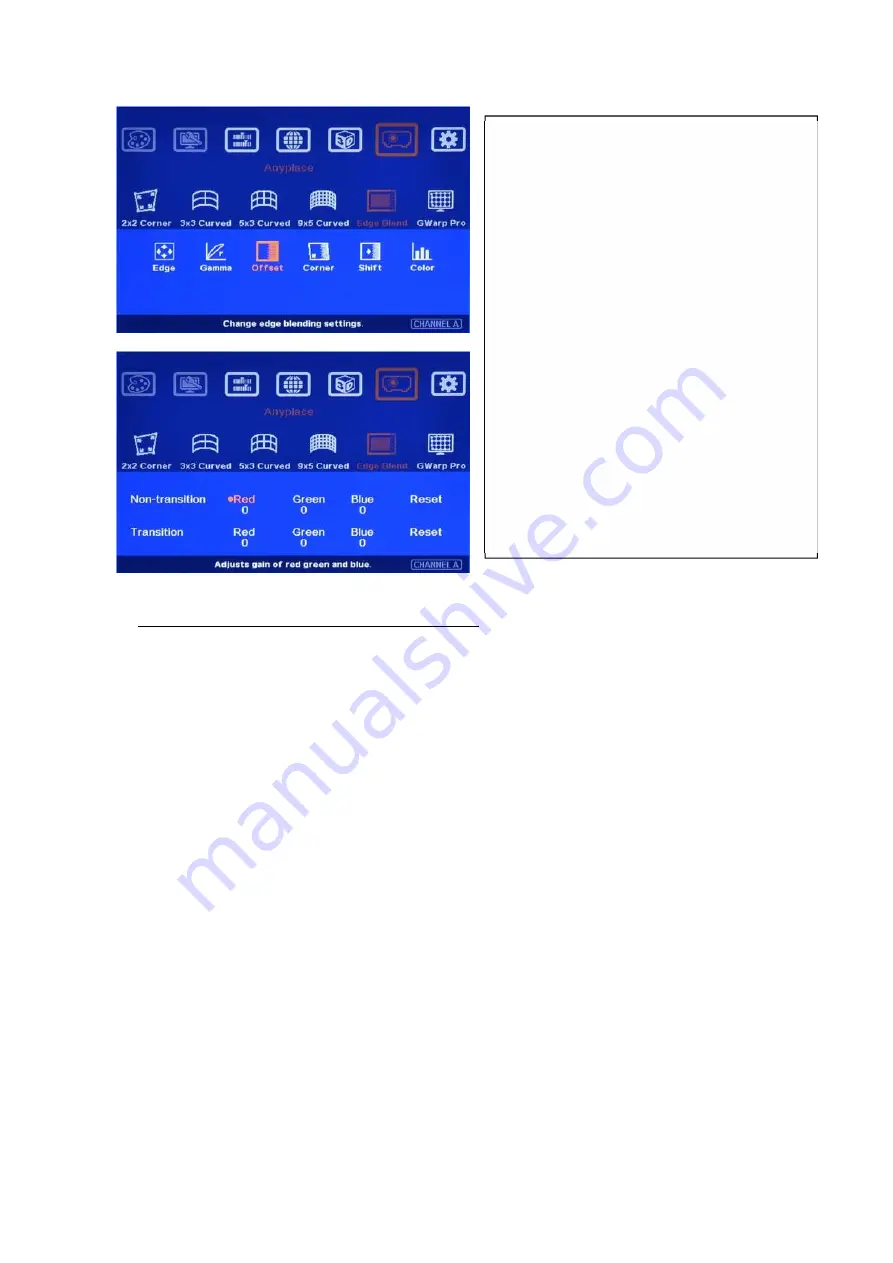
User can find [Non-transition] and
[Transition] offset adjustment menu
。
Under each menu, user can adjust RGB
offset value in Transition and Non-
transition area to balance the color
difference.
Usually, user needs to raise RGB offset
value in Non-transition area (about 20-40
in DLP and 50-70 in LCD projector).
Once color difference is found, user
needs to adjust different RGB offset
value on Transition and Non-transition
area to eliminate the color difference.
User can adjust color in [Transition] area
but can’t reduce the level. It is light
leakage from projector.


