59
Service
CAUTION
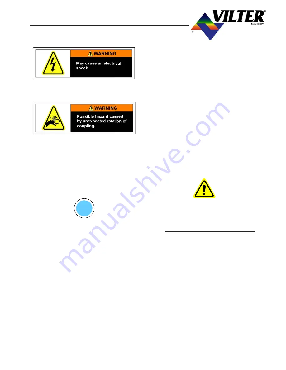
May cause an electrical shock!
E) On VSG units, loosen and remove bolts
holding the compressor to the base.
Keep compressor alignment shims together
and mark the locations with a permanent
marker. On VSG with C- flange the motor/C-
flange/compressor assembly must be sup-
ported with a chain fall or other lifting device,
before the bolts holding the compressor to
the C-flange adapter can be removed.
F)
Install appropriate lifting eye into the threaded
hole on the top of the compressor.
Verify unit is properly secured to avoid
compressor from falling.
Re-verify all piping and electrical are properly
disconnected prior to lifting unit.
G)
Lift compressor from the base, verify the
amount of room needed for clearance and
weight of the bare compressor when the com-
pressor is removed from the unit.
0.03
INSTALLATION OF THE
COMPRESSOR
A) After the work has been completed, reinstall
the compressor on the base or C-flange
adapter (dependent upon compressor model).
B)
On the VSS units, replace the shims under the
compressor feet. Check for a soft foot. This
is accomplished by tightening down three of
the hold down bolts and checking the clear-
ance under the fourth compressor foot. If
there is clearance, add the appropriate amount
of shims. Tighten down the fourth bolt and
loosen either adjacent bolt and check again
for clearance, adding shims accordingly.
Align the compressor and motor.
On VSR & VSM units, the compressor can be
bolted onto the C-flange adapter and the cou-
pling reinstalled.
On VSR compressors the discharge elbow
should be tightened on the separator first,
before the compressor manifold flange is tight-
ened. This should be done to prevent com-
pressor to motor misalignment.
Replace all electrical, gas and oil connections
removed when servicing the compressor.
0.03
LEAK CHECKING UNIT
Note: Unit can be leak checked before evacua-
tion.
CAUTION
Slowly pressurize the unit from the discharge
side of the compressor. Pressurizing the com-
pressor from the suction side may cause rota-
tion of the compressor without oil supply, which
could lead to internal damage.
A) Use a vacuum pump to evacuate the unit.
B)
Break the vacuum on the unit using refriger-
ant or dry nitrogen and check for leaks. Con-
centrate on areas where work was done.
C)
If no leaks are found, the unit can be returned
to service if refrigerant was used for the leak
detection gas.
If dry nitrogen was used for the leak detec-
tion gas, the nitrogen must be purged from
the unit and step A and B should be repeated,
this time breaking the vacuum with refriger-
ant. The unit may now be returned to ser-
vice.
Summary of Contents for VSM 71-701
Page 1: ...1 VPN 35391S February 2006 Rev 05 Price 60 00...
Page 2: ...2...
Page 20: ...20...
Page 52: ...53 Pre Start Up Check List...
Page 99: ...99 Recommended Spare Parts List...
Page 104: ...104 Gate Rotor...
Page 110: ...110 Main Rotor VSS...
Page 112: ...112 Main Rotor VSR...
Page 114: ...114 Slide Valve Cross Shafts and End Plate...
Page 118: ...118 Capacity Slide Volume Slide Carriage Assembly Slide Valve Carriage Assembly...
Page 134: ...134 Miscellaneous Frame Components VSS Screw Compressor VSR Mini Screw Compressor...
Page 138: ...138 C FlangeAdapter Components 630 620 610 640 601 641 630 601 620 610 640 641 642 650 651...
Page 140: ...140 Replacement Parts Tools...
Page 144: ...144 GaterotorAssembly...
Page 148: ...148 Main Rotor Slide Valve Cross Shafts and End Plate Models 71 401 Only Counter clockwise...
Page 152: ...152 Main Rotor Slide Valve Cross Shafts and End Plate Model 501 701 Only Clockwise...
Page 154: ...154 Volume Ratio Capacity Slide Carriage Assembly Slide Valve Carriage Assembly...
Page 158: ...158 Miscellaneous Frame Components Model VSM 501 701 Model VSM 71 401...
Page 160: ...160 Replacement Parts Accessories Housing Accessories C Flange Assembly...
Page 166: ...166 Haight Pumps...
Page 170: ...3 Refrigerating Specialties Division...
Page 236: ......
Page 237: ......
Page 238: ......
Page 243: ......
Page 244: ...168...


