BULLETIN 30-11 /
Page 3
Wiring
— Check the electrical specifications of the coil to be sure
they correspond to the available electrical service.
The 1/2" BX conduit connection or junction box on the coil may be
rotated to any position by loosening the coil hexscrew. Solenoid
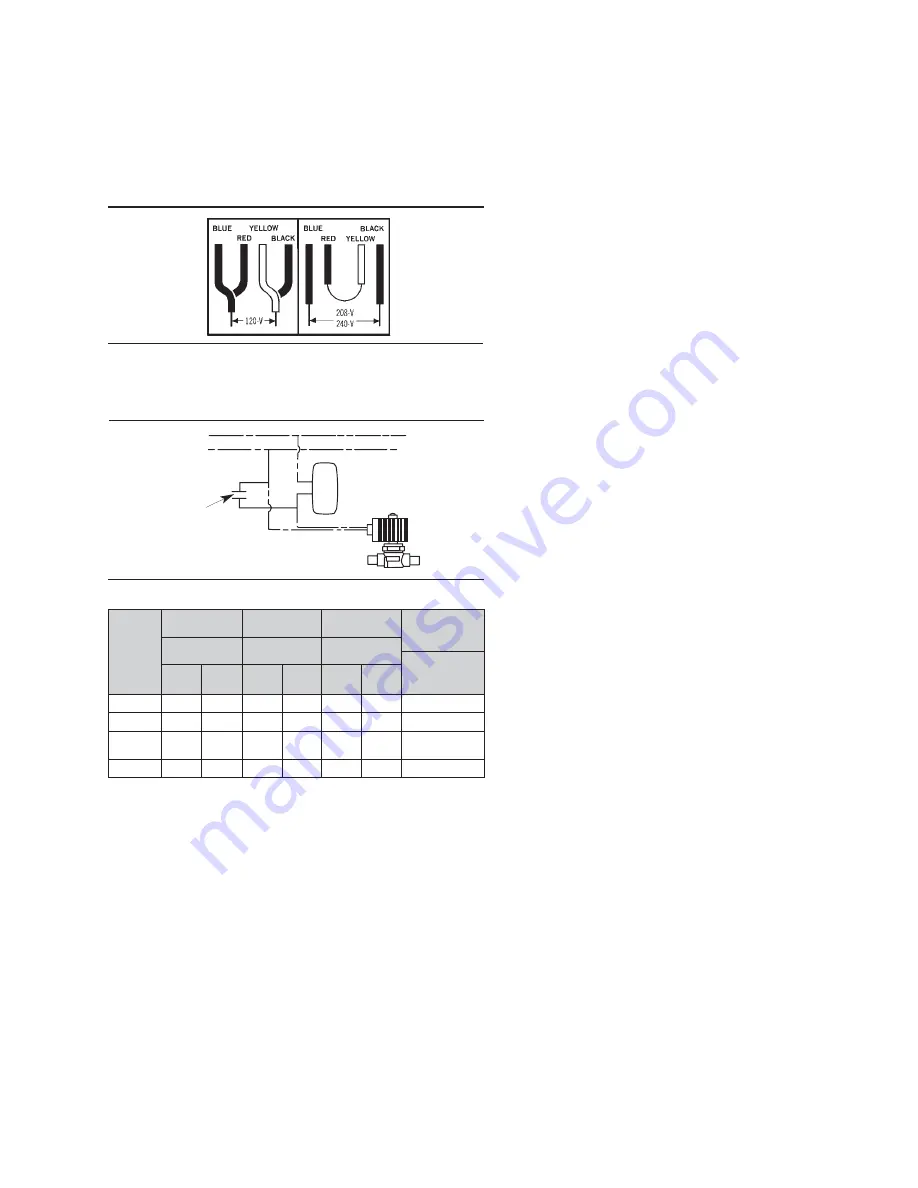
valves with four-wire dual voltage coils have a wiring diagram decal,
Figure 3, on the coil housing or bracket. This illustrates which wires
to connect for either 120, 208 or 240 volt operation. Wiring and
fusing (when used) must comply with prevailing local and national
wiring codes and ordinances.
Direct Current Valves
— A surge protector is supplied with each
solenoid valve with a 115 volt DC coil. The surge protector is
necessary to absorb the high counter-voltage generated when the
circuit is broken, thereby protecting the electrical contacts of the
thermostat. It should be wired as shown in Figure 4.
SERVICING INSTRUCTIONS
CAUTION
— Dangerous hydraulic pressures may develop if a hand
valve is installed in the liquid line ahead of the solenoid valve and the
hand valve is closed while the solenoid valve is closed. This may
cause extrusion of the teflon seat in the disc. Extrusion may cause the
valve to fail to open, fail to close and/or have excessive seat leakage.
Also the line between these two valves should be pumped down
completely before disassembling the solenoid valve for service.
NOTE:
The optional manual lift stem is designed to prevent damage to
the disc. If the stem is turned in too far, the threads become disengaged.
These threads can be re-engaged by applying slight outward force
while turning counterclockwise. A thread stop is provided to prevent
the stem from backing all the way out of the assembly. Back the stem
to the stop and replace the seal cap when service is complete.
TYPICAL MALFUNCTIONS
There are only three possible malfunctions:
1. Coil burnout.
2. Failure to open. 3. Failure to close.
Each is discussed.
1. COIL BURNOUT
Coil burnouts are extremely rare unless caused by one of the
following:
1. Improper electrical characteristics.
2. Continuous over-voltage, more than 10%.
3. Under-voltage of more than 15%. This applies only if the
operating conditions are such that the reduced MOPD causes
stalling of the plunger, which results in excessive current draw.
4. Incomplete magnetic circuit due to the omission of parts such
as: coil housing, coil sleeves, coil spring, coil housing bottom
plate or plunger on the KC model coil and coil yoke, coil
backplate or plunger on the MKC molded model coils.
5. Mechanical interference with plunger movement which may be
caused by a deformed enclosing tube.
6. Voltage spike.
7. Valve ambient exceeds 120°F.
8. Fluid or gas temperatures greater than 240°F, while the valve
ambient is 120°F.
2. FAILURE TO OPEN (Normally Closed Types)
1. Coil burned out or an open circuit to coil connections.
2. Improper electrical characteristics.
3. In pilot operated valves, dirt, scale or sludge may prevent the
piston, disc or diaphragm from lifting. This could also be
caused by a deformed body.
4. High differential pressure that exceeds the MOPD rating of the
valve.
5. Diameter reduction of synthetic seating material in pilot port
because of high temperatures and/or pressures, or severe
pulsations. Contact Sporlan Valve Co., Washington, MO.
The problem of dirt can be avoided by installing a Sporlan
Catch-AIl
®
Filter-Drier
upstream from the solenoid valve. The
Catch-AII
®
Filter-Drier
will retain much smaller particles than a
conventional strainer.
Use a Sporlan strainer for water applications upstream of every
industrial solenoid valve.
3. FAILURE TO CLOSE
1. Valve is oversized. Pilot operated valves may fail to close due
to low pressure drop.
2. In pilot operated valves, dirt, scale or sludge may prevent the
piston, disc or diaphragm from closing. This could also be
caused by a deformed body.
3. Held open by the manual lift stem.
4. In pilot operated valves only, a damaged pilot port may prevent
closing.
5. A floating disc due to severe discharge pulses, contact Sporlan
Valve Co., Washington, MO.
6. Have voltage feedback to the coil after the coil de-energizes.
MISCELLANEOUS
1. Liquid Hammer
— Industrial solenoid valves, or other liquid
line valves, may cause liquid hammer when installed on liquid
lines with high liquid velocities. If this occurs, it can be minimized
by the use of larger pipes, (i.e. lower velocities), or a standpipe
installed in the piping near the solenoid valve inlet. Commercially
available shock absorbers may also be used to reduce this noise.
Recommended maximum velocity is approximately 300 fpm.
2. AC Hum
— This problem may be caused by a loose coil housing
on a KC model coil. On rare occasions this may be caused by
loose coil sleeves, in which case deforming them slightly will
eliminate the hum. A loose coil hex screw or coil locknut may
cause this problem on the MKC molded model coils.
Foreign material between the magnetic top plug and the plunger
in the Types A3, E3, W3, E5, B6, E6, W6, B9, E9, B10, E10, B14,
E14, W14, B19, E19, W19, B25, E25, W25, B33, E33, E34 and
E42 Series Solenoid valves may cause AC hum also.
On water applications, deposits may accumulate in the valve
which could cause AC hum. This may be eliminated by cleaning
or flushing the valve.
3. Leak Testing
— Special care should be taken when leak testing
valves with synthetic gaskets. Gasket materials are slightly
permeable. Leak rates of 0.5 oz. per year should be acceptable.
Note the sensitivity of electronic leak detectors. Most have the
capability of finding a leak smaller than 0.05 oz. per year. Double
check small seal leaks with soap bubbles or a halide torch if
possible.
Do not over tighten the enclosing tube locknut.
If a
leak occurs, change the gasket and verify the metal surfaces have
a clean smooth finish.
L
I
O
C
T
I
K
c
0
6
-
0
5
/
v
4
2
c
0
6
-
0
5
/
v
0
2
1
c
0
6
-
0
5
/
v
0
4
2
r
e
m
r
o
f
s
n
a
r
T
g
n
i
t
a
R
s
e
r
e
p
m
A
-
t
l
o
V
t
n
e
r
r
u
C
s
e
r
e
p
m
A
t
n
e
r
r
u
C
s
e
r
e
p
m
A
t
n
e
r
r
u
C
s
e
r
e
p
m
A
f
o
%
0
0
1
r
o
F
D
P
O
M
d
e
t
a
r
e
v
l
a
V
f
o
-
n
I
h
s
u
r
-
d
l
o
H
g
n
i
-
n
I
h
s
u
r
-
d
l
o
H
g
n
i
-
n
I
h
s
u
r
-
d
l
o
H
g
n
i
1
-
C
K
M
9
.
1
3
6
.
9
3
.
4
1
.
9
1
.
9
0
.
0
6
1
-
C
K
M
O
9
.
1
4
9
.
2
4
.
1
2
.
0
2
.
0
1
.
0
6
2
-
C
K
M
2
-
C
K
M
O
1
.
3
4
.
1
0
6
.
6
2
.
1
3
.
3
1
.
0
0
1
3
-
C
K
9
.
7
9
.
1
7
.
1
1
4
.
3
8
.
1
2
.
0
5
2
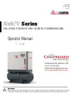
TRANSFORMER SELECTION
■
Figure 3
■
Figure 4
Surge Protector
Thermostat
D. C. Line
Summary of Contents for VSM 71-701
Page 1: ...1 VPN 35391S February 2006 Rev 05 Price 60 00...
Page 2: ...2...
Page 20: ...20...
Page 52: ...53 Pre Start Up Check List...
Page 99: ...99 Recommended Spare Parts List...
Page 104: ...104 Gate Rotor...
Page 110: ...110 Main Rotor VSS...
Page 112: ...112 Main Rotor VSR...
Page 114: ...114 Slide Valve Cross Shafts and End Plate...
Page 118: ...118 Capacity Slide Volume Slide Carriage Assembly Slide Valve Carriage Assembly...
Page 134: ...134 Miscellaneous Frame Components VSS Screw Compressor VSR Mini Screw Compressor...
Page 138: ...138 C FlangeAdapter Components 630 620 610 640 601 641 630 601 620 610 640 641 642 650 651...
Page 140: ...140 Replacement Parts Tools...
Page 144: ...144 GaterotorAssembly...
Page 148: ...148 Main Rotor Slide Valve Cross Shafts and End Plate Models 71 401 Only Counter clockwise...
Page 152: ...152 Main Rotor Slide Valve Cross Shafts and End Plate Model 501 701 Only Clockwise...
Page 154: ...154 Volume Ratio Capacity Slide Carriage Assembly Slide Valve Carriage Assembly...
Page 158: ...158 Miscellaneous Frame Components Model VSM 501 701 Model VSM 71 401...
Page 160: ...160 Replacement Parts Accessories Housing Accessories C Flange Assembly...
Page 166: ...166 Haight Pumps...
Page 170: ...3 Refrigerating Specialties Division...
Page 236: ......
Page 237: ......
Page 238: ......
Page 243: ......
Page 244: ...168...


