Refrigerating Specialties Division
2
Principles of Operation (See Fig. 1)
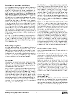
The inlet pressure enters the space under the diaphragm
through passage N. When the force created by the
pressure exceeds the force of the range spring, the
diaphragm is lifted off the pilot seat allowing pressure to
enter on top of the power piston. This causes the power
piston to move downward forcing the modulating plug to
open and modulate to maintain constant inlet pressure.
An increase in inlet pressure lifts the diaphragm further,
allowing more pressure on top of the power piston and
opening the valve wider. A decrease in inlet pressure
causes the diaphragm to move closer to the pilot seat
reducing the pressure on the top of the power piston and
causing the closing spring to reduce the valve opening.
The pressure on top of the power piston is controlled by
the flow through the pilot seat and the bleed off through
the bleed hole in the power piston and through the
clearance between the piston and cylinder. A minimum of
0.14 bar (2 psig) pressure drop across the valve is required
to open it fully.
The A4A Inlet Pressure Regulator therefore opens on a
rise in the inlet pressure above its set point and closes on
a drop in inlet pressure below its set point. The inlet
pressure set point is not appreciably affected by variations
in the outlet pressure.
Manual Opening Stem
All Type A4A Regulators are provided with a manual
opening stem. To open the regulator manually, back the
stem out (turn counter-clockwise) until it stops. To put the
regulator into automatic operation, turn the stem in
(clockwise) until only the flats on the stem protrude from
the packing nut. Always retighten packing nut after
changing position of the manual opening stem.
Installation
All regulators are packed for maximum protection. Unpack
carefully. Check the carton to make sure all flanges and
other items are unpacked. Save the enclosed instructions
for the installer and eventual user.
Do not remove the protective coverings from the inlet and
outlet of the regulator until the regulator is ready to be
installed. Protect the inside of the regulator from moisture,
dirt and chips before and during installation. When welded
or brazed flange connections are used, all slag, scale and
loose particles should be removed from the flange interior
before the regulator is installed between the flanges. It is
advisable to install a close-coupled companion strainer
(RSF) at the inlet of the regulator to help protect it from
any foreign material in the system.
The A4A Series of Regulators will give optimum
performance if mounted in a horizontal line in a vertical
position with the manual opening stem on bottom. Where
other positions are desired, the factory should be
consulted; please give application and piping details. The
regulator must be installed with the arrow on the valve
body pointing in the direction of the fluid flow for the
regulator to function properly. Backward flow through the
regulator is uncontrolled and will vary with the valve model
and the reverse pressure drop encountered. The regulator
is not a check valve.
Tighten the flange bolts and nuts evenly to provide proper
seating of the flange gasket and to avoid damage to
gaskets or flanges. (See Flange Bolt Torque Table, p. 12)
Avoid using the regulator flange bolts to stretch or align
pipe. Even the heavy-duty iron alloy body of an A4A can
be distorted, causing the precision parts to bind.
The regulator should be installed in a location where it is
easily accessible for adjustment and maintenance. The
location should be such that the regulator can not be easily
damaged by material handling equipment. When it is
necessary to insulate the regulator (and companion
strainer), the insulation should be installed to provide
access to the regulator (and companion strainer) for
adjustment and maintenance. Proper indicating gauges
should be installed to be easily visible to the operating
engineer for system checking and adjusting purposes.
Disassembly and Assembly
Refer to the exploded view (Fig. 2) for parts discussed in
this section.
Before disassembling any A4A type regulator, read the
information in this bulletin and Bulletin RSB, Safety
Procedures for Refrigerating Specialties Division
Refrigeration Control Valves.
Before a regulator is removed from the line or
disassembled in the line, make sure that all refrigerant
has been removed from the regulator, including the
bonnet, where applicable, and the close coupled strainer.
The regulator must be isolated from the rest of the system
in a safe manner. When pumping down to remove the
refrigerant, the manual opening stem 33A must be turned
out (counter clockwise) to make sure the valve is open.
All A4A Regulators
General Procedure
The construction of the regulator and the method of
disassembly are relatively simple, but some procedures
must be followed to avoid damage. The following describes
the procedure for the basic A4A; special instructions for
other styles will be included in other appropriate sections.
Summary of Contents for VSM 71-701
Page 1: ...1 VPN 35391S February 2006 Rev 05 Price 60 00...
Page 2: ...2...
Page 20: ...20...
Page 52: ...53 Pre Start Up Check List...
Page 99: ...99 Recommended Spare Parts List...
Page 104: ...104 Gate Rotor...
Page 110: ...110 Main Rotor VSS...
Page 112: ...112 Main Rotor VSR...
Page 114: ...114 Slide Valve Cross Shafts and End Plate...
Page 118: ...118 Capacity Slide Volume Slide Carriage Assembly Slide Valve Carriage Assembly...
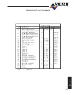
Page 134: ...134 Miscellaneous Frame Components VSS Screw Compressor VSR Mini Screw Compressor...
Page 138: ...138 C FlangeAdapter Components 630 620 610 640 601 641 630 601 620 610 640 641 642 650 651...
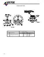
Page 140: ...140 Replacement Parts Tools...
Page 144: ...144 GaterotorAssembly...
Page 148: ...148 Main Rotor Slide Valve Cross Shafts and End Plate Models 71 401 Only Counter clockwise...
Page 152: ...152 Main Rotor Slide Valve Cross Shafts and End Plate Model 501 701 Only Clockwise...
Page 154: ...154 Volume Ratio Capacity Slide Carriage Assembly Slide Valve Carriage Assembly...
Page 158: ...158 Miscellaneous Frame Components Model VSM 501 701 Model VSM 71 401...
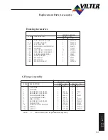
Page 160: ...160 Replacement Parts Accessories Housing Accessories C Flange Assembly...
Page 166: ...166 Haight Pumps...
Page 170: ...3 Refrigerating Specialties Division...
Page 236: ......
Page 237: ......
Page 238: ......
Page 243: ......
Page 244: ...168...

