46
Operation
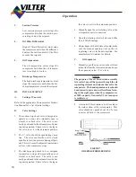
FIGURE 4.
TYPICAL WATER COOLED OIL COOLER
DIAGRAM
The solenoid valve provides positive water
shut-off when the compressor is not in opera-
tion.
A temperature of 150°F is considered high in
most circumstances and the compressor is pro-
tected by a safety control to prevent operation
of the compressor above this temperature.
Unless otherwise specified, the oil cooler is
sized for an 85°F water inlet temperature and
10°F temperature rise.
2.
Liquid Injection Oil Cooling.
The components are furnished with liquid in-
jection for a typical system. The liquid sole-
noid valve opens whenever the compressor is
in operation. The thermostatic expansion valve
controls the flow of liquid refrigerant to the
compressor injection port in response to the
discharge temperature. The discharge tempera-
ture is maintained at a minimum of 120°F with
a maximum of 140°F. The discharge tempera-
ture can be adjusted either of two ways. First,
the small outlet pressure regulator can be used
to adjust superheat. Normally, this regulator
should be adjusted to maintain 70 psig pres-
sure at the external equalizing port of the ex-
pansion valve. Raising the pressure beyond
70 psig tends to raise the discharge tempera-
ture, while lowering the pressure lowers the
discharge temperature. Secondly, the standard
superheat adjusting screw on the thermostatic
expansion valve can be used to adjust the dis-
charge temperature.
FIGURE 5.
TYPICAL LIQUID INJECTION OIL COOLING
SCHEMATIC DIAGRAM
Liquid injection cooling on booster compressors is
handled in the following manner. Using high pres-
sure liquid, the point of injection can be the dis-
charge line and no horsepower penalty is paid by
injecting liquid into the compressor discharge line.
The high pressure gas source normally used for the
pressure regulator would be compressor discharge
pressure. Since, on a booster unit, this intermediate
pressure is very rarely as high as the nominal set-
ting of 70 psig, high stage discharge gas is used.
On high stage compressors, the liquid is injected
directly into the compressor. However, there is a
horsepower penalty when the liquid is injected into
the compressor. This will vary with refrigerant and
operating condition. The liquid is injected into the
compressor at a point in the compressor cycle that
minimizes the brake horsepower penalty.
3.
V-PLUS Oil Cooling System
This system consists of a liquid pump, shut-off
valves, motor, solid state variable speed controller
and solid state temperature controller. This method
of oil cooling is not available on the VSM or VSR
compressor units.
The pump and solenoid valve cycle on and off in
parallel with the compressor drive motor. The tem-
perature controller receives a temperature signal
from the sensor located in the discharge and oil lines
and in turn, sends a signal to the motor speed con-
troller. As the oil and desupserheating load varies,
1/4” Fine
Adjustment Valve
Summary of Contents for VSM 71-701
Page 1: ...1 VPN 35391S February 2006 Rev 05 Price 60 00...
Page 2: ...2...
Page 20: ...20...
Page 52: ...53 Pre Start Up Check List...
Page 99: ...99 Recommended Spare Parts List...
Page 104: ...104 Gate Rotor...
Page 110: ...110 Main Rotor VSS...
Page 112: ...112 Main Rotor VSR...
Page 114: ...114 Slide Valve Cross Shafts and End Plate...
Page 118: ...118 Capacity Slide Volume Slide Carriage Assembly Slide Valve Carriage Assembly...
Page 134: ...134 Miscellaneous Frame Components VSS Screw Compressor VSR Mini Screw Compressor...
Page 138: ...138 C FlangeAdapter Components 630 620 610 640 601 641 630 601 620 610 640 641 642 650 651...
Page 140: ...140 Replacement Parts Tools...
Page 144: ...144 GaterotorAssembly...
Page 148: ...148 Main Rotor Slide Valve Cross Shafts and End Plate Models 71 401 Only Counter clockwise...
Page 152: ...152 Main Rotor Slide Valve Cross Shafts and End Plate Model 501 701 Only Clockwise...
Page 154: ...154 Volume Ratio Capacity Slide Carriage Assembly Slide Valve Carriage Assembly...
Page 158: ...158 Miscellaneous Frame Components Model VSM 501 701 Model VSM 71 401...
Page 160: ...160 Replacement Parts Accessories Housing Accessories C Flange Assembly...
Page 166: ...166 Haight Pumps...
Page 170: ...3 Refrigerating Specialties Division...
Page 236: ......
Page 237: ......
Page 238: ......
Page 243: ......
Page 244: ...168...


