background image

17

FAST HEAT, INC. 

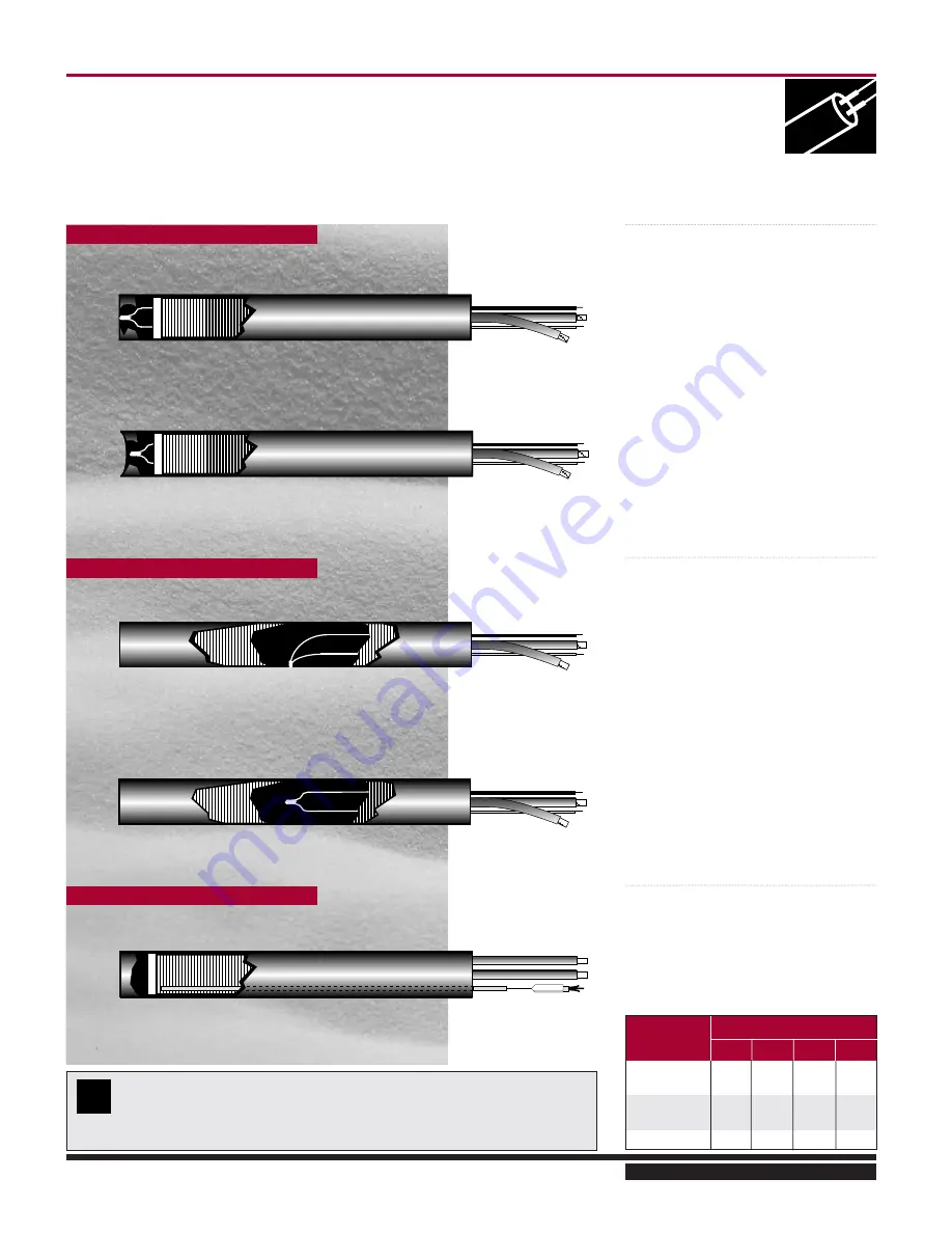
THERMOCOUPLE LOCATION

CARTRIDGE HEATERS

BOTTOM GROUNDED

For fast response, heater is positioned in a
blind hole or where material flows past or
encompasses the heater. 

The end disk is always welded in place.

Machined flat up to 

1

2

“ (12.7 mm) dia. 

BOTTOM UNGROUNDED

Where circumstances are such that an
ungrounded thermocouple is required.

CENTER UNGROUNDED

The thermocouple is positioned internally
and ungrounded to monitor the heater 
temperature.

Generally used in research and
development applications. 

REMOVEABLE THERMOCOUPLE

The thermocouple is inserted down a
hypotube for easy removal.

T/C  AT BOTTOM

T/C  AT CENTER

HTR

GROUNDED

UNGROUNDED

DIA.

BOTTOM CENTER BOTTOM CENTER

1

/

4

” (6.4 mm)

Y

N

Y

Y

5

/

16

” (7.9 mm)

Y

N

Y

Y

3

/

8

” (9.5 mm)

Y

Y

Y

Y

1

/

2

” (12.7 mm)

Y

Y

Y

Y

5

/

8

” (15.9 mm)

Y

Y

Y

Y

T/C AVAILABILITY

All heaters shown are Hi-Temp 
10” leads, type “J” T/C standard, 
type “K” T/C is available.

T/C available in all Standard Cartridge 
heaters. Located at bottom ungrounded 
and center ungrounded.

HI-TEMP T/C LOCATION AVAILABILITY

Hi-Temp

Hi-Temp

Hi-Temp

Hi-Temp

Hi-Temp

?

CENTER GROUNDED

Selected when a fast response is required. 

The thermocouple can be located in any
position along the length of the heater.
Standard location is midway along the
length with approximately 

1

4

” (6.4 mm)

cold section on either side of the junction.

Not available on 1/4” diameter heaters.

REMOVEABLE THERMOCOUPLE

Summary of Contents for VSM 71-701

Page 1: ...1 VPN 35391S February 2006 Rev 05 Price 60 00...

Page 2: ...2...

Page 3: ...uipment Damage can occur in shipment however For this reason the units should be thoroughly inspected upon arrival Any damage noted should be reported immediately to the Transportation Company This wa...

Page 4: ...alocarbon Refrigerant Systems 24 Evacuating The System 24 UNIT OIL CHARGING 25 Oil For Single Screw Compressors 25 SYSTEM REFRIGERANT CHARGING 25 Low Side Equipment 26 Compressors 26 Condensers 26 Con...

Page 5: ...il Pressure 49 Discharge Pressure 49 Suction Pressure 50 Oil Filter Differential 50 Oil Temperature 50 Discharge Temperature 50 INITIALSTART UP 50 Setting of Controls 50 Valve Settings 50 Oil Separato...

Page 6: ...E ACTUATOR 80 CONVERSION INSTALLATION OF ACTUATOR 80 COMMAND SHAFT ASSEMBLY REMOVAL 80 COMMAND SHAFTASSEMBLY INSTALLATION 81 COMMAND SHAFT BEARINGAND O RING SEAL REPLACEMENT 81 COMMAND SHAFT BEARING A...

Page 7: ...32 Tubing and Fittings 132 Miscellaneous Frame Components 134 C Flange Adapter Components 138 Replacement Parts Tools 140 VSM Replacement Parts Section 143 Gaterotor Assembly 144 Shaft Seal 147 Main R...

Page 8: ...ood blocks under the base skid so that water does not collect inside the base perimeter or low spots in the tarp All compressor stop valves are to be closed to isolate the compressor from the remainde...

Page 9: ...moisture indicator shows that the desiccant has lost its effectiveness as by a change in color the bag should be opened and fresh replacement desiccants installed Whenever the motor cannot be sealed...

Page 10: ...12 months from date of installation at the initial end users location whichever occurs first In addition Seller provides the following extended warranties a three 3 years from the date of shipment on...

Page 11: ...OF THE CONTRACT PRICE IN THE EVENT THAT ANY WARRANTY OR WARRANTY REMEDY FAILS OF ITS ESSENTIAL PURPOSE OR IS HELD TO BE INVALID OR UNENFORCE ABLE FOR ANY REASON IN CONSIDERATION OF THE OTHER PROVISION...

Page 12: ...tion statements are merely good faith estimates Unless otherwise stated on Seller s Order Acknowledgment all shipments are F O B Seller s factory Seller reserves the rights to make installment deliver...

Page 13: ...ATION OF THE OTHER PROVISIONS OF THIS AGREEMENT THE PARTIES AGREE THAT ALL LIABILITY LIMITATIONS WILL NEVERTHELESS REMAIN IN EFFECT Governing Law and Dispute Resolution This Agreement shall be governe...

Page 14: ...re manufactured by others are not warranted by Seller but rather Seller merely passes through the manufacturer s warranty to Buyer SELLER EXPRESSLY DISCLAIMS ALL OTHER WARRANTIES WHETHER EXPRESS OR IM...

Page 15: ...seller hereunder which are manufactured by someone else are not warranted by Seller in any way but Seller agrees to assign to Buyer any warranty rights in such products that the Seller may have from...

Page 16: ...s enters the compressor housing through the top inlet flange at the driven end of the unit The driven end of the compressor hous ing is flooded with gas at suction pressure The gas enters the open end...

Page 17: ...eginning of the compression process With the slide moved all the way out to the suction end of the screw the 100 position the compression pro cess begins immediately after the gate rotor tooth enters...

Page 18: ...zards MandatoryAction Sign Verification Communicates an action to be taken to AVOID hazard Prohibition Symbol Note The symbols that appear on this page are used throughout the manual to help identify...

Page 19: ...essors 25 SYSTEM REFRIGERANT CHARGING 25 Low Side Equipment 26 Compressors 26 Condensers 26 Controls 26 Initial Charging High Side Charging 26 MAINTENANCE SUGGESTIONS 27 Daily 27 Weekly 27 Monthly 27...

Page 20: ...20...

Page 21: ...mounted on struc tural steel Place the entire unit on the floor on a concrete pad and securely bolt in place Review local codes and ASHRAE Safety Code for Me chanical Refrigeration Bolt holes are loca...

Page 22: ...copper at the design temperature Some local codes forbid the use of Type L Therefore be fore installation be sure to check local require ments Never use type M as it does not have adequate wall thickn...

Page 23: ...advisable to check local codes as they may differ Before testing may proceed sev eral things must be done First if test pressures exceed the settings of the system relief valves or safety devices the...

Page 24: ...em operates best when only refrigerant is present Steps must be taken to re move all air water vapor and all other non condensables from the system before charging it with refrigerant A combination of...

Page 25: ...chargers are available for this purpose Once the unit has been started and is operating above 50 capacity oil may have to be added to bring the oil level to the normal operating point With the unit o...

Page 26: ...illing of the system is much faster Low side charging is usually reserved for adding only small amounts of refrigerant after the system is in operation High side charging of refrigerant into the sys t...

Page 27: ...ure and temperature readings 3 Check micronic oil filter inlet and outlet pressures for excessive pressure drop Change filter when pressure drop exceeds 45 psi or every six months whichever oc curs fi...

Page 28: ...over em phasized Similarly when any service operations are performed on the system care should be exer cised to insure all opened flanges are tightened all plugs that were removed are replaced with a...

Page 29: ...lustrations above The drill fixture is designed so that the hole for the spring will always be drilled on the opposite side from the cast in Vilter name on the bonnet From the outside of the valve the...

Page 30: ...haft does not allow enough room to install the short bolts in the hub after hub mounting install the bolts and disc pack before mounting hub on shaft B Straight Bore 1 Install key s in the shaft If th...

Page 31: ...install key s Remount hub drawing it up the shaft to the 0 set point Continue to advance hub up the taper to the desired axial position Use the indicator as a guide only A pre set axial stop device ca...

Page 32: ...isc packs on the hubs with one bolt through the disc pack aligned with a clearance hole in the hub In stall the short bolts through the hub disc pack bevel washer or link and secure with a lock out NO...

Page 33: ...t our from between the two disc packs B Remove one short bolt from the disc pack hub connection and reinstall it through a hub clear ance hole and into the hole in the disc pack Put the nut on This wi...

Page 34: ...on Vantage control panel com pletely 3 If not already done mount the slide valve actuator per Vilter Actuator set up for Capacity and Volume Slide Mo tors Next wire the actuator per the attached wirin...

Page 35: ...running and 5V when it is still Thus as stated earlier the actuator voltage will fluctuate during calibration After the actuator has been calibrated 0V output will correspond to the minimum position a...

Page 36: ...ring the mechanical stop position 22 Pulse the INC button to carefully move the slide valve until the millivolt readout saturates or stops increasing This is around 9500 millivolts 8400 millivolts for...

Page 37: ...Because the motor is connected to the slide valve by gears knowing the motor position means knowing the slide valve position During calibration the position sensor records the high and low count of m...

Page 38: ...or or grey cable There is an intermittent failure of the position sensor The motor brake is not working prop erly see theory section above Clean the optocoupler slots with a Q Tip and rubbing alcohol...

Page 39: ...r mal switch is tripping Recalibrate Get the motor brake to where it op erates freely and then recalibrate Replace the actuator Try to realign or replace the ac tuator Adjust the photochopper so that...

Page 40: ...ns listed in The mo tor will not move in either direction Stripped gears inside the gear motor or the armature has come un pressed from the armature shaft Replace the actuator See above Replace the ac...

Page 41: ...rting Stopping and Restarting the Compressor 47 Slide Valve Control 48 Slide Valve Motor Location 49 Oil Separator Heater 49 Econ O Mizer Controls 49 Safety Setpoints 49 Oil Pressure 49 Discharge Pres...

Page 42: ...y for any detrimental affects those lubricants may have on the equipment or system performance and durability Should a lubrication related system issue occur with the use of non Vilter oils Vilter may...

Page 43: ...s 45 psi whichever occurs first The pressure drop across the filter is read on the microprocessor panel Check the pressure drop and record it daily To prepare for the removal of the filter shut down t...

Page 44: ...Removal VSS and VSM Units after 5 1 00 when using Vilter Part Numbers 3109A 16 Duplex or 3110A 39 Duplex oil filter housings Isolate the bowl to be worked on by turning handle The handle will cover t...

Page 45: ...in place CAUTION When changing filter discard clogged filter only Save and reuse spring plate and center ing piece This filter MUST be installed with the spring plate A compressor that is allowed to o...

Page 46: ...on valve can be used to adjust the dis charge temperature FIGURE 5 TYPICAL LIQUID INJECTION OIL COOLING SCHEMATIC DIAGRAM Liquid injection cooling on booster compressors is handled in the following ma...

Page 47: ...block and bleed valves that are used to recalibrate the pres sure transducers To use the block and bleed valves to recalibrate the pressure transducers the block valve is shut off at the unit and the...

Page 48: ...CW 1 36 490 5 325 0 82 295 3 200 VSS 1801 CCW CW CCW CW 1 36 490 5 325 0 82 295 3 200 VSM 71 CW CCW CW CCW 0 80 288 3 141 0 45 162 1 767 VSM 91 CW CCW CW CCW 0 80 288 3 141 0 45 162 1 767 VSM 101 CW C...

Page 49: ...setpoint See appropriate Microprocessor Instruction Manual 3 Oil Separator Heater The oil separator heater keeps the oil in the separator from becoming too viscous and helps to boil off refrigerant e...

Page 50: ...e adjusted to minimize oil loss when compressor stops 3 The discharge stop check valve is designed to operate as a stop valve manually open or closed or a check valve The valve is nor mally positioned...

Page 51: ...m out as indicated by the chart below CLOSED In the manually Closed Postion the stop check is operating as a conven tional stop valve not allowing flow in either direction OPEN In the manually Open Po...

Page 52: ...53 Pre Start Up Check List...

Page 53: ...the regulator from high stage discharge gas f or the Thermostatic Expansion Valve b V PLUS A high pressure liquid source must be run to the V PLUS inlet Some subcooling is desirable A high pressure fl...

Page 54: ...for this coil should come from a source which will be de energized with the compressor disconnect 4 A dry contact from control relay K 19 must be wired to the oil pump motor starter coil This dry con...

Page 55: ...ROTOR ASSEMBLY 75 INSPECTION OF SLIDE VALVE ASSEMBLIES IN THE COMPRESSOR 76 REMOVALSLIDE VALVE 76 CARRIAGE ASSEMBLIES 76 INSTALLATION OF SLIDE VALVE CARRIAGEASSEMBLIES 77 CAPACITYAND VARIABLE VOLUME...

Page 56: ...OVAL 88 INSTALLATION OF RETROFIT COMMAND SHAFT BEARING AND O RING SEAL 89 REPLACEMENT FOR RETROFIT CONTROL ASSEMBLIES 89 COMMAND SHAFT BEARING AND O RING SEAL REASSEMBLY 90 LIQUID INJECTION PLUG REPLA...

Page 57: ...the accessory section on de tails of how to adjust regulator The reg ulator should be adjusted to maintain ap proximately 70 psig on the external equal izing connection of theTX valve At this setting...

Page 58: ...otor to prevent the unit from start ing Put a lock on the disconnect switch and tag the switch to indicate that maintenance is being performed C Isolate the unit by manually closing the dis charge Sto...

Page 59: ...t If there is clearance add the appropriate amount of shims Tighten down the fourth bolt and loosen either adjacent bolt and check again for clearance adding shims accordingly Align the compressor and...

Page 60: ...arings A Shut down and de pressurize the unit as outlined in section 0 01 B Main rotor bearing float 1 Remove the coupling guard then re move the center member from the cou pling 2 Attach a dial indic...

Page 61: ...401 0 045 VSM 501 THRU 701 0 045 VSR111THRUVSS601 0 045 VSS751 VSS901 0 055 VSS1051 VSS1201 0 060 VSS1501 VSS1801 0 060 E Readings could be higher than 0 020 If readings is greater than 0 030 over tab...

Page 62: ...in the holes Remove the remaining bolts and side cover There will be some oil drainage when the cover is removed C Turn the main rotor so a driving edge of any one of the main rotor grooves is even wi...

Page 63: ...k wise The thrust bearings and housing as sembly will be pulled off the shaft and out of the frame G Remove the bolts on the roller bearing hous ing Thread two bolts into the jack screw holes provided...

Page 64: ...re the compressor for servicing as out lined in section 0 01 B Remove the upper bolt from the side cover and install a guide stud in the hole Remove the remaining bolts and side cover There will be so...

Page 65: ...st bearings These control the clearance between the shelf and gate ro tor blades These must be kept with their respective parts for that side of the compres sor G Remove the bolts from the roller bear...

Page 66: ...ing housing 112 with a new O ring 141 Tighten the bolts 152 to the recommended torque value C When installing the thrust bearing housing 113 a new O ring 142 must be used when the housing is installed...

Page 67: ...te the gate rotor to find the tightest spot It should be between 0 003 0 004 Make adjustments if necessary It is preferable to shim the gate rotor blade looser rather than tighter against the shelf No...

Page 68: ...helf and blade D Check the clearance between the entire gate rotor blade and the shelf rotate the gate ro tor to find the tightest spot It should be between 0 003 0 004 Make adjustments if necessary I...

Page 69: ...ble If the gate rotor support has a small diameter pin only the small diameter bushing can be used with it Additionally a large diameter pin cannot be used in a gate rotor support machined for a small...

Page 70: ...ement between the gate rotor and support E For installation of the gate rotor assembly and setting of gate rotor clearance refer to section 1 02 1 05 GATE ROTOR THRUST BEARING REMOVAL A Refer to secti...

Page 71: ...efer to section 1 02 B For installation of thrust bearings on VSM units 1 Install retainer in the back of the inner race of one of the thrust bearings The back of the inner race is the narrower of the...

Page 72: ...r bearing race 125 from the gate rotor sup port 110 1 02 GATE ROTOR ROLLER BEARING INSTALLATION A Match up the part numbers on the inner race to the part numbers outer race Press the bear ing race num...

Page 73: ...ing the shaft seal cover 218 Insert two of the bolts into the threaded jacking holes to assist in removing the cover There will be a small amount of oil drainage as the cover is removed C Remove the r...

Page 74: ...l the carbon cartridge part of the seal in the seal cover clean the seal cover remove protective plastic from the carbon cartridge do not wipe or touch the carbon face Lubricate the sealing O ring wit...

Page 75: ...A spray bottle filled with clean compressor oil may be used to lubricate the faces of the seals without touching the seal E Install a new O ring on the seal cover mak ing sure the O ring is placed in...

Page 76: ...ve clamps and slide valve carriage through the gas bypass opening The clearance should be less than 0 002 D If the slide valves are worn in excess of the tolerances the factory should be contacted 3 1...

Page 77: ...lide valve assembly in the bore of frame and use the slide hammer to slowly tap the carriage into position Re positioning slide valves once inside bore may aid installation Adjust the carriage so that...

Page 78: ...ere is only one set of volume or capacity slide valves However all information on removing the volume or capacity control assemblies is applicable to all units 4 01 OPTICAL SLIDE VALVE ACTUATOR REMOVA...

Page 79: ...mpressor use of the other key slot may be required to align the bracket holes with the threaded mounting plate holes C Slide the collar until it is flush with the end of the actuator shaft Check to ma...

Page 80: ...e four 10 holes in the existing mounting plate that will be utilized to attach the actua tor must be in good condition A 10 24 N C tap can be utilized to clean out the threaded holes D Install the key...

Page 81: ...B Install the actuator mounting plate with the four socket head cap screws and Nord Lock washers securing it with proper torque C The unit can now be leak checked as out lined in section 0 03 4 07 CO...

Page 82: ...move the remaining bolts note length and location of bolts and take off the discharge manifold Note Mainfold has dowel pins to locate it on the compressor housing Therefore re move manifold straight b...

Page 83: ...ack shafts and the rack The jam nuts on the end of the slide valve rack shaft should be tight E Check for loose or broken roll pins in gears Loose nuts Roll pins Rack to clamp Rack to spacer clamp Che...

Page 84: ...s Install clamps spacers and bolts on both sides Tighten the bolts to the recommended torque values B The slide valve sets must be synchronized on VSS and dual gate VSM units Both slide valve racks fo...

Page 85: ...d with a brake If it is necessary to oper ate the control motors manually the brake must be disengaged The brake can be disengaged by pushing on the motor shaft on the cone end The shaft should be cen...

Page 86: ...nifold 4 22 INSTALLATION A Install the command shaft assembly with a new O ring on the manifold Make sure the command shaft tongue is engaged in the cross shaft slot Rotate the bearing housing so the...

Page 87: ...meters The unit can now be evacuated and leak checked as out lined in section 0 03 4 23 POTENTIOMETER REMOVAL GEAR MOTOR ONLY A Remove the cover for the slide valve control assembly Mark and disconnec...

Page 88: ...le potentiometer lead goes to the red wire and brown potentiometer lead goes to the black wire Recalibrate the potentiometer ac cording to the appropriate Microprocessor operating manual The remaining...

Page 89: ...g housing so the vent holes points down to prevent water and dust from entering the vent B Install the new motor plate 415 and the four socket head cap screws 457 and Nord Lock washers 477 securing it...

Page 90: ...O ring when assem bling Press the command shaft bearing 435 onto the command shaft IMPORTANT Do not press on outer bearing race when install ing the bearing on to the command shaft C Insert the comman...

Page 91: ...ich holds the steel plug in position To remove the steel plug the crushed Teflon pel let must be dug out from the top of the steel plug Care must be taken that all of the Teflon is removed from the th...

Page 92: ...VSR 151 301 25905BC VSS 451 25905BB VSS 451E NONE VSS 601 25905BA VSS 601E 25905BA VSS 751 25905CB VSS 751E 25905CB VSS 901 25905CA VSS 901E 25905CA VSS 1051 25905DB VSS 1051E 25905DC VSS 1201 25905DA...

Page 93: ...Lock lock washer sets are used in many areas in both the VSR and VSS screw compressors that require a vibration proof lock washer B The lock washer set is assembled so the course serrations that resem...

Page 94: ...ength 18 Diameter 6 1 8 A Characteristics 1 The outside of the filter element is covered with a perforated metal sur face 2 At each end of the filter there is a large thick elastomeric seal 3 The hous...

Page 95: ...of the element 2 One end of the element is solid while the other has a pilot hole with a cap tive o ring 6 03 KT 722 FILTER ELEMENTS Vilter Part Number KT 722 Tank O Ring 2176AJ Usage VSR Compres sors...

Page 96: ...ors 3 1 00 to present Length 16 A Characteristics 1 Pleated type element with a screen covering the surface of the element 2 One end of the element is solid while the other has a pilot hole with a cap...

Page 97: ...els with 30 and larger oil separators 3 1 00 to present Length 39 C Characteristics 1 Pleated type element with a screen covering the surface of the element 2 One end of the element is solid while the...

Page 98: ...I I I I I I CONTROL CALIBRATION Transducers I I I I I I I I I I I I I I RTD s I I I I I I I I I I I I I I COMPRESSOR Inspect Compressor I I I I I I I Bearings I Key I Inspect R Replace S Sample Notes...

Page 99: ...99 Recommended Spare Parts List...

Page 100: ...April 2000 2 Dual Element Filter Tank 112R Oil Filter X 35197A Filter Tank Cover Gasket 1 Single or Dual Element Filter Tank 112R Included with 1833C X X 3109A Duplex Housing 16 Bowl or 30 Oil Separa...

Page 101: ...nge Gasket 2 Haight X X X 3022DU 20 GPM Oil Pump w Bracket 1 Was 3022D Before 1995 req s 2913E hub 111R Oil Pump X X X 3022CU Replacement Shaft Seal 1 24U Oil Pumps AFTER 4 19 02 111R 1548AA Flange Ga...

Page 102: ...KT781A Shaft Seal Kit 1 VSR111 VSS601 VSM 501 701 111R Other Refrig X KT781B Shaft Seal Kit 1 VSS751 1201 111R X KT781C Shaft Seal Kit 1 VSS1501 1801 111R X KT781D Shaft Seal Kit 1 VSM 71 401 111R Sl...

Page 103: ...to 5 1 95 115 Slide Valve Carriage Assembly 120 Capacity Control Actuating Motor and Command Shaft 122 Slide Valve Actuating Motor and Command shaft Before 5 1 95 126 Volume Ratio Control Actuating Mo...

Page 104: ...104 Gate Rotor...

Page 105: ...A 2 25519A 118 GATE ROTOR COVER GASKET 1 25259A 1 25259A 2 25259A 2 25259A 119 WASHER 1 25007A 1 25007A 2 25007A 2 25007A 120A BUSHING SMALL DOWEL PIN 1 25006A 1 25006A 2 25006A 2 25006A 120B BUSHING...

Page 106: ...2 25311A 2 25311A 118 GATE ROTOR COVER GASKET 2 25088A 2 25088A 2 25132A 2 25132A 119 WASHER 2 25086A 2 25086A 2 25086A 2 25086A 120A BUSHING SMALL DOWEL PIN 2 25087A 2 25087A 2 25104A 2 25104A 120B B...

Page 107: ...A 116 BALL BEARING COVER 2 25351A 2 25351A 117 GATE ROTOR COVER 2 25354A 2 25354A 118 GATE ROTOR COVER GASKET 2 25790A 2 25790A 119 WASHER 2 25788A 2 25788A 120A BUSHING SMALL DOWEL PIN 2 25104A 2 251...

Page 108: ...108 Shaft Seal Shaft Seal With Stationary Carbon Face Important Item 244 Tappered ID Faces Outward Shaft Seal Baffle Assemmbly...

Page 109: ...5269B 1 25670A 219 SHAFT SEAL Ammonia 1 25043A 1 25043A 1 25043B 1 25378A 219 SHAFT SEAL Halo 1 25432B 1 25432B 1 25432C 1 25432E 230 OIL SEAL 1 25040A 1 25040A 1 25064A 1 2930B 244 TEFLON SEAL 1 2593...

Page 110: ...110 Main Rotor VSS...

Page 111: ...2865A 2 2865A 2 2865E 2 2865E 2 2865G 2 2865G 2 2865J 2 2865J 246 ROLLER BEARING 1 2864A 1 2864A 1 2864D 1 2864D 1 2864D 1 2864D 1 2864J 1 2864J 250 RETAINING RING n a n a 1 2867M 1 2867M 1 2867M 1 28...

Page 112: ...112 Main Rotor VSR...

Page 113: ...15 OUTER BEARING RET 1 25001C 2 25001C 216 INNER BEARING RET 1 25062B 1 25062B 220 ENDPLATE ASSY 1 A25851BC 1 A25851BC 245 BEARING BALL 2 2865E 2 2865E 246 BEARING ROLLER CYL 1 2864A 1 2864A 251 RETAI...

Page 114: ...114 Slide Valve Cross Shafts and End Plate...

Page 115: ...N PIN 4 1193D 4 1193D 4 1193D 4 1193D 269 EXPANSION PIN 4 2981AA 4 2981AA 4 2981AA 4 2981AA 270 PIPE PLUG 2 2606E 2 2606E 2 2606E 2 2606E 286 SOCKET HEAD CAP SCREW 4 2795F 4 2795F 8 2795F 8 2795F 297...

Page 116: ...606E 286 SOCKET HEAD CAP SCREW 8 2795F 8 2795F 8 2795F 8 2795F 297 SET SCREW 2 2060J 2 2060J 2 2060J 2 2060J 298 SET SCREW 2 2060H 2 2060H 2 2060H 2 2060H NOTE Not pictured Slide Valve Cross Shafts Pr...

Page 117: ...A 222 GEAR 4 25027A 4 25027A 226 RACK CLAMP 4 25913C 4 25913C 228 SPACER 4 25033C 4 25033C 267 DOWEL PIN 2 2868B 2 2868B 268 EXPANSION PIN 4 1193D 4 1193D 269 EXPANSION PIN 4 2981AA 4 2981AA 270 PIPE...

Page 118: ...118 Capacity Slide Volume Slide Carriage Assembly Slide Valve Carriage Assembly...

Page 119: ...SEPARATE VOL CAP 0 n a 0 n a 4 25022A 4 25022A 343B COVER ONE PIECE CAST 0 n a 0 2 25399A 2 25399A 345A GASKET SEPARATE VOL n a CAP COVERS 0 n a 0 n a 4 25021A 4 25021A 345B GASKET ONE PIECE CAST COVE...

Page 120: ...2 25123A n a n a n a n a 345A GASKET SEPARATE VOL CAP COVERS 2 25124B 2 25124B 4 25124C 4 25124C 345B GASKET ONE PIECE CAST COVER 2 25902A 2 25902A 2 25901A 2 25901A 346 GASKET SEPARATE VOL CAP COVERS...

Page 121: ...25782A 341 CAPACITY PISTON SHAFT 2 25784A 2 25784A 342 VOLUME PISTON SHAFT 2 25783A 2 25783A 343B COVER 2 25690A 2 25690A 345B GASKET 2 25384A 2 25384A 347 PISTON SLEEVE 4 25786A 4 25786A 350 PISTON...

Page 122: ...pacity Control Actuating Motor and Command Shaft Note Steel Bushing until 10 25 04 then modified housing See note above New housing design starting 10 25 04 for all command shaft assemblies OpticalAct...

Page 123: ...5830A 1 25830A 1 25830A 1 25830A 432 CLAMP FOR ITEM 424 1 2013A 1 2013A 1 2013A 1 2013A 433 BUSHING DIV 2 1 25853A 1 25853A 1 25853A 1 25853A 435 BALL BEARING 1 2908A 1 2908A 1 2908A 1 2908A 436 SLEEV...

Page 124: ...0 BUSHING 1 25809A 1 25809A 1 25809A 1 25809A 431 SPACER 1 25830A 1 25830A 1 25830A 1 25830A 432 CLAMP FOR ITEM 424 1 2013A 1 2013A 1 2013A 1 2013A 433 BUSHING DIV 2 1 25853A 1 25853A 1 25853A 1 25853...

Page 125: ...25757A 430 BUSHING 1 25809A 1 25809A 431 SPACER 1 25830A 1 25830A 432 CLAMP FOR ITEM 424 1 2013A 1 2013A 433 BUSHING DIV 2 1 25853A 1 25853A 435 BALL BEARING 1 2908A 1 2908A 436 SLEEVE BEARING 1 2585...

Page 126: ...otor and Command shaft Before 5 1 95 429 450 425 418 452 412 430 439 431 440 410 447 446 419 417 458 443 459 458 416 420 421 OR 408 408 463 451 407 403 405 404 454 419 443 455 463 415 453 435 438 411...

Page 127: ...n a n a n a 425 POTENTIOMETER n a n a n a n a n a n a n a n a 429 GASKET 2 25757A 2 25757A 2 25757A 2 25757A 430 O RING 2 2176W 2 2176W 2 2176W 2 2176W 431 O RING 2 2176X 2 2176X 2 2176X 2 2176X 435...

Page 128: ...rolActuating Motor and Command Shaft Optical Actuator Note Steel Bushing until 10 25 04 then modified housing New housing design starting 10 25 04 for all command shaft assemblies See Note above See p...

Page 129: ...1 25809A 1 25809A 1 25809A 1 25809A 431 SPACER 1 25830A 1 25830A 1 25830A 1 25830A 432 CLAMP FOR ITEM 424 1 2013A 1 2013A 1 2013A 1 2013A 433 BUSHING DIV 2 1 25853A 1 25853A 1 25853A 1 25853A 435 BAL...

Page 130: ...BUSHING 1 25809A 1 25809A 1 25809A 1 25809A 431 SPACER 1 25830A 1 25830A 1 25830A 1 25830A 432 CLAMP FOR ITEM 424 1 2013A 1 2013A 1 2013A 1 2013A 433 BUSHING DIV 2 1 25853A 1 25853A 1 25853A 1 25853A...

Page 131: ...25757A 430 BUSHING 1 25809A 1 25809A 431 SPACER 1 25830A 1 25830A 432 CLAMP FOR ITEM 424 1 2013A 1 2013A 433 BUSHING DIV 2 1 25853A 1 25853A 435 BALL BEARING 1 2908A 1 2908A 436 SLEEVE BEARING 1 25853...

Page 132: ...58 568 567 556 555 555 OR 555 558 555 555 555 563 564 555 555 565 566 555 Slide Valve Piston Equalizing Lines VSS 451 VSS 601 VSS 1051 VSS1201 VSS 751 VSS 901 Seal Chamber Oil Line VSS 451 VSS1201 VSS...

Page 133: ...5D 3 13375D 556 STRAIGHT 1 13229D 1 13229D 2 13229D 2 13229D 557 TEE RUNNING 1 1509A 1 1509A 1 1509A 1 1509A 558 HEX BUSHING 1 13231AA 1 13231AA 1 1101H 1 1101H 559 HEX BUSHING 0 n a 0 n a 1 1101K 1 1...

Page 134: ...134 Miscellaneous Frame Components VSS Screw Compressor VSR Mini Screw Compressor...

Page 135: ...n a n a n a 530 O RING 2 2176AB 2 2176AB 2 2176AB 2 2176AB 532 O RING 2 2176BA 2 2176BA n a n a n a n a 535 PIPE PLUG 1 4 MPT 1 2606C 1 2606C n a n a n a n a 535 PIPE PLUG 3 8 MPT 1 2606D 1 2606D 2 26...

Page 136: ...25199C 522 LOCKING WASHER 1 25004A 1 25004A 1 25004A 1 25004A 523 LOCKING TAB 1 25005A 1 25005A 1 25005A 1 25005A 526 ORIFICE PLATE 1 25223CB 1 25223CA 1 25223DB 1 25223DB 529 WAVE SPRING 1 2912E 1 2...

Page 137: ...ANGE GASKET 1 25199C 1 25199C 522 LOCKING WASHER 1 25004C 1 25004C 523 LOCKING TAB 1 25005C 1 25005C 530 O RING 2 2176J 2 2176J 536 PIPE PLUG 1 2 MPT 3 2606E 3 2606E 537 PIPE PLUG 1 1 4 MPT 2 13163G 2...

Page 138: ...138 C FlangeAdapter Components 630 620 610 640 601 641 630 601 620 610 640 641 642 650 651...

Page 139: ...FLANGEADAPTER 610 KEY 1 25039AA 1 25039AA 620 HEX HEAD CAP SCREW 8 2796C 8 2796C 630 LOCKWASHER PAIR 8 3004H 8 3004H 640 CONNECTOR 1 13229C 1 13229C 641 TUBE 1 4 O D x 6 LONG 0 5 Ft S1589AA 0 5 Ft S15...

Page 140: ...140 Replacement Parts Tools...

Page 141: ...917 SOCKET HEAD CAP SCREW 2 2795W 2 2795W 2 2795W 2 2795W 918 HEX NUT 3 13228F 3 13228F 3 13228F 3 13228F MODEL NUMBER ITEM DESCRIPTION VSS 751 VSS901 VSS 1051 VSS 1201 QTY VPN QTY VPN QTY VPN QTY VPN...

Page 142: ...B 1 A25699B 901B HEX HEAD CAP SCREW 4 2796A 4 2796A 901C RAIL SIDE 2 25698C 2 25698C 901D LOCK WASHER 4 13165B 4 13165B 910 PULLER BAR 1 25204C 1 25204C 911 PULLER SHOE 1 25157E 1 25157E 912 PUSHER SH...

Page 143: ...e Valve Cross Shafts and End Plate Models 71 401 148 Main Rotor Slide Valve Cross Shafts and End Plate Models 501 701 152 Slide Valve Carriage Assembly 154 Actuating Motor with Optical Sensor and Comm...

Page 144: ...144 GaterotorAssembly...

Page 145: ...8B 1 25408B 1 25408B 117 GATE ROTOR COVER 1 25416B 1 25416B 1 25416B 118 GATE ROTOR COVER GASKET 1 25259B 1 25259B 1 25259B 119 WASHER WAVE SPRING 1 3203A 1 3203A 1 3203A 120 DAMPER 1 25760A 1 25760A...

Page 146: ...1 26019B 117 GATE ROTOR COVER 1 26021B 1 26021B 1 26021B 118 GATE ROTOR COVER GASKET 1 25259C 1 25259C 1 25259C 119 WASHER 1 25007A 1 25007A 1 25007A 120 DAMPER 1 25760A 1 25760A 1 25760A 121 SHIM 0 0...

Page 147: ...USING 1 25410B 1 25269A 219 SHAFT SEAL 1 A 1 A 230 OIL SEAL 1 2930C 1 25040A 244 TEFLON SEAL 1 25939A 1 25939A 252 RETAINER RING 1 2928M 1 2928M 260 O RING 1 2176U 1 2176F 261 O RING 205 Only 1 2176AE...

Page 148: ...148 Main Rotor Slide Valve Cross Shafts and End Plate Models 71 401 Only Counter clockwise...

Page 149: ...A 25409AC A 25409AC 243 SHIM 0 010 A 25409AD A 25409AD A 25409AD 244 TEFLON RING 1 25939A 1 25939A 1 25939A 248 CHECK VALVE 1 3120A 1 3120A 1 3120A 249 CHECK VALVE 1 3120B 1 3120B 1 3120B 250 RETAINI...

Page 150: ...SHIM 0 010 A 25409AD A 25409AD A 25409AD 244 TEFLON RING 1 25939A 1 25939A 1 25939A 248 CHECK VALVE 1 3120A 1 3120A 1 3120A 249 CHECK VALVE 1 3120B 1 3120B 1 3120B 250 RETAINING RING 2 2867T 2 2867T 2...

Page 151: ...151 See Next Page for Models 501 701 Main Rotor Slide Valve Cross Shafts and End Plate V S M Parts List...

Page 152: ...152 Main Rotor Slide Valve Cross Shafts and End Plate Model 501 701 Only Clockwise...

Page 153: ...3 SHIM 0 010 A 25255AD A 25255AD A 25255AD 244 TEFLON RING 1 25929B 1 25929B 1 25929B 248 CHECK VALVE 1 3120A 1 3120A 1 3120A 249 CHECK VALVE 1 3120B 1 3120B 1 3120B 250 RETAINING RING 2 2867B 2 2867B...

Page 154: ...154 Volume Ratio Capacity Slide Carriage Assembly Slide Valve Carriage Assembly...

Page 155: ...ACITY PISTON SHAFT 1 25018B 1 25019A 342 VOLUME PISTON SHAFT 1 25018C 1 25018A 350 PISTON RING SET 2 2953AE 2 2953AA 355 EXPANSION PIN 2 1193PP 2 1193PP 359 PIPE PLUG 3 2606D 3 2606D 360 LOCK WASHER P...

Page 156: ...156 Actuating Motor with Optical Sensor and Command Shaft Kit assemblies are as follows A25975A VSM71 401 A25975B VSM 501 701...

Page 157: ...1 2176W 445A O RING 1 2176W 1 2176W 446 O RING 1 2176X 1 2176X 450 RETAINING RING 1 2866D 1 2866D 451 RETAINING RING 1 2867C 1 2867C 457 SOCKET HEAD CAP SCREW 4 2795M 4 2795M 466 SOCKET HEAD CAP SCREW...

Page 158: ...158 Miscellaneous Frame Components Model VSM 501 701 Model VSM 71 401...

Page 159: ...LATE n a 1 25004D 523 LOCK WASHER n a 1 3004H 528 ECON O MIZER PLUG 2 25419A 2 25397K 530 O RING n a 2 2176BF 535 PIPE PLUG 7 2606E 2 2606D 536 PIPE PLUG 1 13163F 6 2606E 537 PIPE PLUG 1 13163G 1 1316...

Page 160: ...160 Replacement Parts Accessories Housing Accessories C Flange Assembly...

Page 161: ...06E 343 PISTON COVER 1 25724B MODEL NUMBER ITEM DESCRIPTION VSM 71 401 VSM 501 701 QTY VPN QTY VPN 1 C FLANGE 1 A 1 A 2 ADAPTER 1 A 1 A 3 HEX HEAD CAP SCREW 8 2796F 8 2796F 4 HEX HEAD CAP SCREW 4 2796...

Page 162: ...162 Replacement Tools MODEL NUMBER ITEM DESCRIPTION ALL VSM 71 401 ALL VSM 501 701 QTY VPN QTY VPN 901 GATEROTOR STABILIZER 1 25742A 1 25742B 902 SEAL INSTALLATION TOOL 1 25455A 1 25455B...

Page 163: ...Inlet Pressure Regulators CARTRIDGE HEATERS SPORLAN Strainers VIKING PUMP Pumps and Pressure Relief Valves FLUID POWER ENERGY Thermostatic Valves SPORLAN Solenoid Valve and Thermostatic Expansion Valv...

Page 164: ...carbon face and the matting face of the seal will need to be inspected for crack ing or excessive wear If they are damaged the seal must be replaced at this time 3 Replace cap o ring 3 at this time 4...

Page 165: ...een discontinued and upgraded to the U series When placing an order for a new pump and had the D old series pump you will be required to upgrade to an U and a new Hub will also need to be purchased Vi...

Page 166: ...166 Haight Pumps...

Page 167: ...2 Buna Neoprene Viton 8 O Ring 1 Buna Viton Neoprene Kalrez Teflon 9 Shaft Pinion Assy std 1 9 Shaft Pinion Assy OBB 1 10 Pinion 1 11 Shaft 1 12 Key 1 13 Rotor C I Standard 1 14 Case 1 1 ports 1 1 4...

Page 168: ...ompressor discharge lines See CK 1 Bulletin 50 10B or for any compressor discharge where a low speed machine discharges into the same downstream header or for use on side port suction lines on a screw...

Page 169: ...3 3 75 4 50 5 81 5 81 7 06 B mm 38 62 95 114 148 148 179 inch 1 50 2 43 3 75 4 50 5 81 5 81 7 06 C mm 27 32 50 60 70 81 89 inch 1 06 1 25 2 2 37 2 75 3 19 3 50 D mm 63 59 79 114 145 157 177 FPT SW inc...

Page 170: ...3 Refrigerating Specialties Division...

Page 171: ...ies Division Defective products or parts thereof returned to the factory with transportation charges prepaid and found to be defective by factory inspection will be replaced or repaired at Refrigerati...

Page 172: ...gulators are suitable for Ammonia R 12 R 22 R 502 and other common refrigerants and fluids approved for use in refrigeration systems All A4 Regulators are pilot operated using upstream pressure for th...

Page 173: ...pled companion strainer RSF at the inlet of the regulator to help protect it from any foreign material in the system The A4A Series of Regulators will give optimum performance if mounted in a horizont...

Page 174: ...11 evenly The ideal tightening torque is 1 5 Kg m 11 ft lbs Valve is now ready to be adjusted for normal operation If close coupled strainer is used it may be cleaned before putting the valve back in...

Page 175: ...202000 1 202000 1 16 19 DiaphragmKit RangeV 202004 1 202004 1 Not A4AO RangeD 202002 1 202002 1 27 Plug Pkg 1 4 NPT 202552 5 202552 5 28 Adapter Only Avail with Kit 1 Only Avail with Kit 1 29 Gasket O...

Page 176: ...il with Kit 2 Only Avail with Kit 2 Only Avail with Kit 2 Only Avail with Kit 2 Only Avail with Kit 2 16 17 19 200771 1 200771 1 200771 1 200771 1 200771 1 200771 1 16 19 202004 1 202004 1 202004 1 20...

Page 177: ...its includes complete set of gaskets plus O Rings if applicable 25 26 29 37 43 45 3 Gasket Kit A4 S4 202112 1 202112 1 lndv l Gaskets 0 Rings Valve Pk g sold pkgd in qtys only as indicated 29 Gasket P...

Page 178: ...1 202051 1 202754 1 202057 1 202060 1 202063 1 3 6 12 19 NOTE 50 Capacity Repair Kit is not available for port sizes 1 1 4 to 4 Capacity reduction can be obtained through use of 29 30 33 37 field ins...

Page 179: ...cleaned or changed frequently When the RSF close coupled companion strainers are used maintain according to instructions in Bulletin 00 10 Moisture in halocarbon systems in particular can cause corro...

Page 180: ...diaphragms Diaphragm follower stuck damaged Clean or replace Install follower carefully or frozen Piston worn too much clearance Replace piston Check for reason If used on liquid check for flash gas R...

Page 181: ...61 10 3 1 1 1 4 216 8 5 216 8 5 261 10 3 1 1 4 256 10 1 256 10 1 300 11 8 1 1 4 203 8 0 248 9 8 410 16 1 1 1 2 256 10 1 256 10 1 304 12 0 1 5 8 1 1 2 307 12 1 307 12 1 364 14 3 251 9 9 287 11 3 464 18...

Page 182: ...254 10 0 76 3 0 102 4 0 53 97 2 1 8 370 14 6 1 5 8 41 27 1 5 8 414 16 3 53 97 2 1 8 404 15 9 140 5 5 251 9 9 307 12 1 114 4 5 140 5 5 2 66 67 2 5 8 429 16 9 66 67 2 5 8 432 17 0 159 6 2 314 12 4 325 1...

Page 183: ...ements Bolt Diameter Valve Port Size Torque 11 mm 7 16 13mm 1 2 3 9 mkg 28 ft lb 16m m 5 8 20 50mm 3 4 2 11 8 mkg 85 ft lb 19m m 3 4 65 75mm 2 1 2 3 14 5 mkg 105 ft lb 22mm 7 8 100mm 4 22 1 mkg 150 ft...

Page 184: ...C A R T R I D G E H E A T E R S Hi Temp Cartridge heaters are designed for optimum performance above and beyond the norm...

Page 185: ...ated Sections OAL Overall Length The subtraction of 3 4 from the overall length in the above equations is a general allowance for the watt density calculations on Standard Cartridge heaters only Hi Te...

Page 186: ...ions U L approved and C S A recognized Top quality ceramic element support Unique winding design allows faster heating and longer life High purity MgO packing for even heat distribution Fiberglass ins...

Page 187: ...variety of termination styles can be adapted to this style of heater When there are termination requirements other than the ones illustrated please contact Fast Heat There may be applications where du...

Page 188: ...Temps 10 25 4 cm leads standard other lengths are available Hi Temp Cartridges are provided with approx 1 25 4 mm sleeving over lead junction as standard 10 25 4 cm leads standard other lengths are a...

Page 189: ...Moisture resistant 10 25 4 cm standard other lengths are available STRAIGHT STRAIN RELIEF SPRING BRAID OVER PAIR OF LEADS SQUARE LOCK ARMOR STRAIN RELIEF CONVOLUTED ARMOR STRAIN RELIEF Hi Temp Standar...

Page 190: ...ainless steel cold rolled or galvanized Bushing material types brass stainless steel or steel 10 25 4 cm leads standard other lengths are available For immersion applications specify sealed end 5 8 to...

Page 191: ...catalog Fast Heat bolt heaters are designed to heat drilled metal surfaces quickly while minimizing heat loss to surrounding areas Each is designed to expand drilled bolts or studs while maintaining...

Page 192: ...ring approximately 3 76 2 mm long 10 25 4 cm leads standard other lengths are available Right angle copper elbow for applications requiring right angle lead exit Moisture resistant seal is optional 10...

Page 193: ...ted and lead wire abrasion protection is required 10 25 4 cm armor standard other lengths are available Order by overall length Leads exit at 90 angle for applications requiring small radius bends lea...

Page 194: ...s with high amps and requiring universal connection capability Screw terminals are attached to external pins Standard Cartridge 10 32 screw terminal on 3 8 to 15 16 9 5 mm 23 8 mm dia Hi Temp 1 2 to 3...

Page 195: ...easy removal T C AT BOTTOM T C AT CENTER HTR GROUNDED UNGROUNDED DIA BOTTOM CENTER BOTTOM CENTER 1 4 6 4 mm Y N Y Y 5 16 7 9 mm Y N Y Y 3 8 9 5 mm Y Y Y Y 1 2 12 7 mm Y Y Y Y 5 8 15 9 mm Y Y Y Y T C...

Page 196: ...l of the Square Cartridge heaters are available in either Hi Temp 85 to 90 watts per square inch depending on the application or Standard 35 to 40 watts per square inch depending on the application St...

Page 197: ...gths are available Clip support helps to minimize lead breakage where leads exit heater 10 25 4 cm leads standard other lengths are available Braided leads exit at 90 angle for applica tions requiring...

Page 198: ...PRECISION STANDARD SQUARE CARTRIDGE HEATERS Our Square Cartridge heaters 3 8 9 5 mm 1 2 12 7 mm and 5 8 15 9 mm square provide more surface area contact than cylindrical types Square Cartridge heaters...

Page 199: ...selected with respect to the design and environment exterior to the heater SHEATH MATERIALS Stainless steel Incoloy CARTRIDGE IMMERSION HEATER Immersion cartridge heaters may be selected when a tubula...

Page 200: ...R 3 4 19 1 mm dia 10 25 4 cm fiberglass leads inside octagonal terminal box 3 4 19 1 mm N P T steel bushing 5 8 15 9 MM DIA OIL WATER 5 8 15 9 mm dia 10 25 4 cm fiberglass leads inside octagonal termi...

Page 201: ...s will not be considered defective The express warranty above constitutes the only warranty of Refrigerating Specialties products and is in lieu of all other warranties expressed or implied written or...

Page 202: ...9 Roll Pin 10 Packing Cartridge 11 O ring Bonnet 12 O ring Stem 13 Packing Nut 14 Bolt Bonnet 15 Screen 16 Bottom Cap 17 Gasket 18 Spring 19 Bolt Cover 20 Plug 2 Bolt body construction SPARE PARTS MM...

Page 203: ...ng water brine and other liquids Excessive pressure drop develops in screen assemblies of 80 and 100 mesh are used for such applications The mesh size of the screen assembly in a strainer is stamped o...

Page 204: ...outlet connection Types 8004 and 8006 strain ers can be bolted direct to the inlet of Type A Thermo static Expansion Valves or Type MA17A3 Solenoid Valves on Ammonia applications The unit is zinc plat...

Page 205: ...Frick and Henry ADVANTAGES These compact check valves offer reliable operation regardless of position Corrosion resistant stainless steel seat disc Metal to metal seats facilitate durable tight closi...

Page 206: ...e close coupled to other matching solenoid valves pressure regulators or strainers by using a Male Adapter Ring and longer bolts supplied when so specified on order INSTALLATION DIMENSIONS D Socket We...

Page 207: ...6 8b Nut HCK4 9 0 10 4 75 0210 8c Nut HCK4 1 4 75 0280 9 Flange FPT SW WN ODS 2 FACTORY Above Kit Consists of 1 Seat Disc 1 72 0069 2 Closing Spring 1 72 0070 3 Seat Cartridge 1 72 0068 4 Seat Cartrid...

Page 208: ...e operating satisfactorily isolate it from the refrigeration system Remove all refrigerant from associated piping and valves Follow the guidelines in the caution section Loosen each flange nut on the...

Page 209: ...PUMP INC A Unit of IDEX Corporation UNMOUNTED PUMP UNITS Foot Mounted GG 4195 HJ 4195 HL 4195 AS 4195 Units Are Designed By The Un Mounted Pump Model Numbers Followed By A Letter s Indicating Drive S...

Page 210: ...ts rotating pump shaft by hand one complete revolution every 30 days to circulate the oil SUGGESTED REPAIR TOOLS The following tools must be available to properly repair Series 4195 and 495 pumps Thes...

Page 211: ...rews in face of bearing housing and turn thrust bearing assembly counterwise and remove from casing See Figure 9 or 10 8 GG HJ HL Remove snap ring from shaft See Figure 9 AS AK AL Remove bearing space...

Page 212: ...HL 4195 and 495 NOT USED ON GG SIZE PUMPS Teflon Registered Trademark of DuPont Dow Elastomers L L C Modifications to pump casing and rotor are required for installation of optional Teflon Mechanical...

Page 213: ...earing from casting 14 Remove seal seat or stationary part of seal from casing 15 Disassemble thrust bearing assembly GG HJ HL Remove outer snap ring from bearing housing and remove ball bearing See F...

Page 214: ...otary portion of mechanical seal prepare and organize rotor shaft head and idler assemblies and appropriate gaskets for quick assembly Once rotary portion of mechanical seal is installed on rotor shaf...

Page 215: ...s head end of pump Drive the bearing into the bore Tap the inner race with a brass bar and lead hammer to position bearing Install inner snap ring AS AK AL Install bearing retainer washer over the sha...

Page 216: ...elief valve and turn end for end Refer to Figures 5 page 2 FIGURE 14 VALVE AS AK and AL SIZES VALVE LIST OF PARTS 1 Valve Cap 6 Valve Body 2 Adjusting Screw 7 Valve Spring 3 Lock Nut 8 Poppet 4 Spring...

Page 217: ...er normal use and service and if such products are returned to Viking s factory at Cedar Falls Iowa transportation charges prepaid and if the products are found by Viking to be defective in workmanshi...

Page 218: ...r ther adjustments are necessary A wide range of temperatures are avail able for water and oil temperature control applications When used in a diverting application on start up the total fluid flow is...

Page 219: ...r factory representative FPE 2010 050803 F2010 F2010X Flow vs Pressure Drop FLOW IN U S GPM SAE 10 100 F 1 1 2 2 PART DESCRIPTION 2010 VALVE BODY See table for material 2020 VALVE COVER See table for...

Page 220: ...he directional arrow on the valve body 3 Place the valve in the line in the proper direction of flow and solder 4 Re assemble as follows see Figures 1 5 and 5A a Place the seat disc into the valve bod...

Page 221: ...t is tightened against the bracket Page 2 BULLETIN 30 11 S E I R E S E V L A V 1 1 1 1 1 G N I S O L C N E E B U T T U N K C O L 5 5 5 5 5 G N I S O L C N E E B U T S W E R C S E V L A V T O L I P Y L...

Page 222: ...hat exceeds the MOPD rating of the valve 5 Diameter reduction of synthetic seating material in pilot port because of high temperatures and or pressures or severe pulsations Contact Sporlan Valve Co Wa...

Page 223: ...used on valve types MA5A MA17A MA32 MA42 MA50 Figure 7 contains a full size plunger gauge and a manual lift stem gauge for easy identi fication of parts Be sure to gauge from the end of the manual li...

Page 224: ...ince system vibration and the weight of the valve may cause valve connections to fracture If a hand valve is located on the outlet side of the TEV it should have a full sized port No restrictions shou...

Page 225: ...er connections When soldering a brass refrigerant distributor to the valve appropriate solders for these connections such as 95 5 Easy Flo Stay Brite 8 or equivalents must be used It is important howe...

Page 226: ...of the valve when the compressor stops If bulb insula tion is used on lines operating below 32 F use non water absorbing insulation to prevent water from freezing around the bulb On brine tanks and wa...

Page 227: ...as pressure can seriously damage the system and endanger human life Never use oxygen or explosive gases Excessive test pressures can shorten the life of the TEV diaphragm Table 1 lists the maximum pre...

Page 228: ...ction line at the bulb location 2 Obtain the suction pressure that exists in the suction line at the bulb location by either of the following methods a If the valve is externally equalized a gauge in...

Page 229: ...ned it is easier to troubleshoot the system The primary cause of difficulty with either the BP or RPB feature is dirt and other foreign materials that restrict or plug them And if the system purpose i...

Page 230: ...the suction line that will reflect the pressure existing in the line at the bulb location Remedy Replace internally equalized valve with one having an external equalizer If external equalizer is insta...

Page 231: ...the off cycle Also a sight glass or See All in the liquid line may indicate continued refrig erant flow for a long period after the compressor has stopped Make certain however that the bubbles are no...

Page 232: ...y insuffi cient air over the coil as a result of an undersized blower dirty air filters or an obstruction in the air stream In addition frost formation on the coil or low entering air temperatures wil...

Page 233: ...n at a time to obtain the lowest superheat with stable operation 6 Moisture As ice forms in a TEV from excessive moisture a very erratic hunt may result Remedy Remove the moisture with the installatio...

Page 234: ...ment can be returned to its original position 3 Using appropriate wrenches or a vise to properly support the valve body remove the element if a replaceable type the bottom cap assembly and the interna...

Page 235: ...E D H r o E D P 1 2 3 1 2 1 9 1 E R H r o E R P 1 2 6 4 1 2 2 1 9 7 6 E R H r o E R P 1 2 3 1 1 1 7 1 2 1 E F U 0 3 2 2 E V U 1 2 5 1 E D U 2 2 6 1 E R U 0 4 2 3 3 2 E F O 3 2 E F U A 3 0 7 5 5 0 4 E...

Page 236: ......

Page 237: ......

Page 238: ......

Page 239: ...LANGE CONNECTIONS 3186ES 2 FPT FLANGE CONNECTIONS 3186FF ST200 2 2 SOCKET WELD FLANGE CONNECTIONS 3186FS ST250 2 2 WELD NECK FLANGE CONNECTIONS 3186GW REPLACEMENT SCREEN KITS SCREEN KIT FOR VALVE SIZE...

Page 240: ...20 42 44 80 40 71 83 150 1 SW 1 1 2 SW 2 SW 2 1 2 BW 1 1 1 2 ORV 25 SOC H1 49qC 120qF ORV 40 SOC H2 49qC 120qF ORV 50 SOC H2 49qC 120qF ORV 65 A H3 49qC 120qF 148H3229 148H3232 148H3235 148H3237 SPARE...

Page 241: ...compressor must be at 100 capacity and at normal operating suction and discharge pressures before the actual port pressure can be determined Once this pressure is known the module stem should be turne...

Page 242: ...els that is economized and controls outlet pressure to economizer port on screw compressor Inlet Module Range A Turn CW to increase back pressure Turn CCW to decrease back pressure M3S Stopping Plug E...

Page 243: ......

Page 244: ...168...

Reviews: