


Page | 20
4.2 Ports and
System Status
LEDs
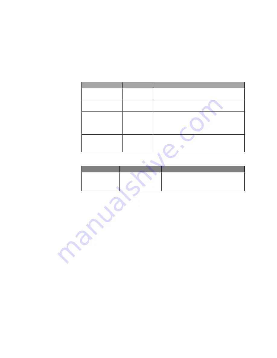
The Vi32226 includes a display panel for system and port indications that
simplify installation and network troubleshooting. The LEDs are located
on left hand side of the front panel for easy viewing. Details are shown
below and described in the following tables.
LED
Conditions Status
TP (Link/ACT)
Yellow
Green when the TP link is good.
Blinks when any traffic is present.
PoE Port 1-24
Green
Green when the port is delivering PoE
power.
Port 25 & 26
Green
On is for 1G Link
Slow blink is for 100Mb/s
Off with link yellow LED on is for
10Mb/s
SFP (Link/ACT) Yellow/
Green
Yellow is for activity
Green is for link
Blinks when any traffic is present.
Table 2: Port Status LEDs
SYSTEM LED Condition
Status
Power
Green
Lit when powered
Table 3: System Status LED
4.3 Console Port
The console port can be used for direct communications with the switch.
If the switch's IP address is lost, it can be recovered without having to
reset the switch to its default settings.
To access the console port: Requires running a terminal program on
your computer.
Terminal set up:
Baud Rate 19,200
Bit Setting
8 Bit
Parity
No Parity
Stop Bit
1 Stop Bit
Flow Control No Flow Control (No Hardware)
Log In
Requires User Name and Password
Once log in has been achieved, type “help” (lower case) for a list of
accessible functions. The current IP can be displayed along with other
functions that can be changed if required.
Summary of Contents for MaxiiNet Vi32226
Page 18: ...Page 18 3 4 Vi32226 Front View 3 5 Vi32226 Rear View ...
Page 32: ...Page 32 After logging in the following page will appear Full Version Lite Version ...
Page 37: ...Page 37 ...
Page 64: ...Page 64 13 1 Drop and Receive Packet 13 2 CRC error packet and Receive Packet ...
Page 83: ...Page 83 ...
Page 90: ...Page 90 ...


