


14
5608 741 - 04
Vitodens Rigid and Flex Venting Systems Installation
General Information
General Rigid Venting Installation
(continued)
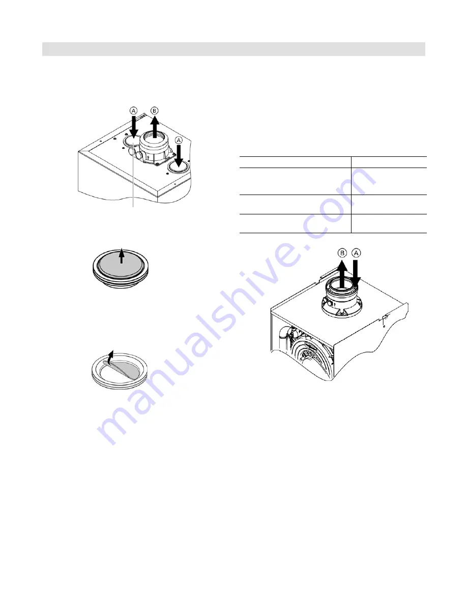
Boiler models Vitodens 200-W WB2B 45, 60, 80, 105,
B2HA 45, 60, 80, 88, 100, 112, 150,
B2HB 45, 57
Legend
A
Combustion air
B
Flue gas
Legend
A
Combustion air
B
Flue gas exhaust
When utilizing the combustion air inlet seal
A
for Vitodens
100 WB1B, 200 B2HA/B and 222 B2TA/B series boilers,
remove the inlet seal
A
, tear out center section and install
the remaining rubber seal back into the air inlet opening.
for Vitodens 100 series and 200 WB2B boilers
for Vitodens 100 series, 200 B2HA/B and 222 B2TA/B boilers
When utilizing the combustion air inlet seal
A
for Vitodens
100 series and 200 WB2B boilers (older models), remove
the plastic center section and leave the rubber seal in place.
This system draws combustion air from the boiler room.
Room/Combustion air enters the boiler at the boiler vent
pipe adaptor through an annular air gap.
If using annular air gap, remove and discard air inlet cover
or use optional opening to the left or right.
The two-pipe venting system draws combustion air
A
through a separate air intake pipe from the outdoors.
Flue gases
B
are discharged to the outdoors via the
single-pipe rigid-pipe and flexible vent system.
The two-pipe system is flexible in the selection of
materials offered by different manufacturers and the
location of the air intake termination.
Read the following exhaust vent/air intake requirements
carefully before commencing with the installation.
Boiler
Flue Gas Exhaust Size
WB1B 26, 35 WB2B 19, 26, 35,
B2HA 19, 28, 35, B2HB 19, 26, 35
B2TA 19, 35, B2TB 19, 35
2 in. (60 mm)
WB2B 45, 60, B2HA 45, 60
B2HB 45, 57
3 in. (80 mm)
WB2B 80, -105
B2HA 80, 88, 100, 112, 150
4
e
in. (110 mm)
Vitodens boilers vent adaptors