background image

7

Initial start−up, inspection and maintenance

Further details regarding the individual steps 

(cont.)

Checking all safety equipment

Check the following settings:
High limit safety cut−out 

max.

 110

º

C

. . 

Control thermostat

max.

 95

º

C

. . . . . . . . . 

Check the control unit adjustments
and change them, if required.

Control unit installation and
service instructions

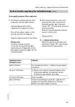
Filling heating system and checking ventilation air supply

1.

Check that the ventilation air
supply is completely
unobstructed.

2.

Check the inlet pressure of the
diaphragm expansion vessel when
the system is cold.

Please note:

If the charge pressure of the
diaphragm expansion vessel is
lower than the static system
pressure, top up with sufficient
nitrogen to raise the charge
pressure (0.1 to 0.2bar) higher
than the static system pressure.
The static pressure corresponds to
the static height.

3.

Open any check valves that may
be fitted.

4.

Top up your heating system with
water and vent until the filling
pressure is higher (0.1 to 0.2bar)
than the inlet pressure of the
diaphragm expansion vessel.

5.

Mark this pressure on pressure
gauge

A

.

Permiss. operating pressure

3bar

. . . . 

6.

Return the check valves to their
operating position.

5692500GB

Summary of Contents for CU3

Page 1: ...structions for heating engineers Vitocrossal 300 Type CU3 Gas fired condensing boiler with MatriX compact gas burner for open flue and balanced flue operation See notes on applicability page 2 5692 500 GB 1 2004 Please keep safe ...

Page 2: ...ll local regulations Repair work It is not permitted to carry out repairs on parts that fulfil a safety function Use only original Viessmann spare parts or equivalent parts that have been approved by Viessmann Initial start up The initial start up must be carried out by the system installer or a designated commissioning engineer All actual values should be recorded in a commissioning service repor...

Page 3: ...ecting manual mode 26 H Manual mode and service display 26 Setting the burner control unit parameters 27 H DIP switch settings 27 H Confirming a parameter set 28 Diagnostics 29 H Fault display 29 H Calling up the fault memory 30 H Faults with fault display 31 H Faults without fault display 35 H Burner control unit flow chart 36 Burner Component summary 38 H Burner control unit connection diagram 4...

Page 4: ...cking CO2 settings 12 C 9 Checking gas valve control pressure 13 C M 10 Checking the draught 13 C 11 Leak testing balanced flue system annular gap check 14 C M 12 Checking ionisation current 14 C I M 13 System shutdown 15 I M 14 Removing burner and checking burner gasket 16 I M 15 Checking burner gauze assembly 17 I M 16 Checking adjusting ignition ionisation electrodes 18 M 17 Disconnecting neutr...

Page 5: ...tions on primary and DHW side for leaks C M 23 Checking diaphragm expansion vessel and system pressure C I M 24 Checking function of all safety valves I M 25 Burner installation 22 C I M 26 Checking tightness of electrical connections C I M 27 Checking all gas equipment for leaks at operating pressure 22 I M 28 Checking the mixer if installed for ease of operation and leaks 22 5692 500 GB ...

Page 6: ...ons Measure the CO value before and after any work on gas appliances to prevent any health hazards and to ensure perfect system condition Please note Record combustion values when the boiler is up to operating temperature min 2 minutes operating time and with the burner hood fitted for open flue mode Operating and service documents 1 Complete and detach the customer registration card H Give the sy...

Page 7: ...essure of the diaphragm expansion vessel when the system is cold Please note If the charge pressure of the diaphragm expansion vessel is lower than the static system pressure top up with sufficient nitrogen to raise the charge pressure 0 1 to 0 2 bar higher than the static system pressure The static pressure corresponds to the static height 3 Open any check valves that may be fitted 4 Top up your ...

Page 8: ...e and Wobbe index Wo from your gas supplier Please note The burner is set up in the factory for natural gas E H With natural gas setting E the boiler can be operated in the Wobbe index range 12 0 to 16 1 kWh m3 43 2 to 58 0 MJ m3 H With natural gas setting LL the boiler can be operated in the Wobbe index range 10 0 to 13 1 kWh m3 36 0 to 47 2 MJ m3 2 If necessary convert the burner in accordance w...

Page 9: ...O ring is inserted into gas restrictor retainer A Insert gas restrictor retainer A into gas combination valve B and secure with screws 7 Remove the self adhesive label for the gas type from the type description supplied and affix over existing label E on gas restrictor retainer A Safety instructions Check all gas connections for leaks 8 Affix label Adjusted for showing the current gas type over ex...

Page 10: ...he gas shut off valve 2 Release upper screw A of the retaining plate on burner control unit B do not fully unscrew and twist burner control unit B aside clockwise 3 Release the screw inside test nipple PE C on the gas combination valve but do not remove and connect the pressure gauge 4 Open the gas shut off valve 5 Check the static pressure it should be between 20 and 50 mbar Record the actual val...

Page 11: ...e boiler close the gas shut off valve remove the pressure gauge and close test nipple PE C with the previously removed screw Refit the mounting plate with the burner control unit Torque 2 Nm 9 Safety instructions Open the gas shut off valve and check test nipple PE and all gas connections for soundness Supply pressure flow pressure Remedy below 15 mbar Do not start up boiler notify your gas supply...

Page 12: ...ual CO2 value with the above CO2 value ranges for the individual gas groups check the gas group with your gas supplier If the actual CO2 value deviates from the stated ranges by more than 1 proceed as follows H Check that the correct gas restrictor has been installed see page 9 H Carry out a leak test on the balanced flue system see page 14 1 Connect a flue gas analyser at boiler adaptor A flue ga...

Page 13: ...e DIP switches see page 27 H Check the flue gas and ventilation air lines H Check pressure limiter B for soundness sealing washers Please note Use suitable test equipment with a range from 0 to 1000 Pa Vacuum pressure is applied to both test nipples The vacuum pressure at the test nipple with the symbol is lower and that at the test nipple with the symbol is higher Connect the pressure gauge accor...

Page 14: ...es out a simple leak test during the initial start up of your system For this it would be sufficient to check the CO2 concentration in the combustion air at the annular gap in the balanced flue pipe The flue pipe is deemed to be sound if the CO2 concentration in the combustion air is lower than 0 2 or if the O2 concentration is at least 20 6 If actual CO2 values are higher or O2 values are lower t...

Page 15: ...d lower rated output For settings of the upper and lower values see page 26 Please note Ionisation current at H upper rated output min 10 mA H lower rated output min 3 mA 8 Record the actual values in the service report see from page 46 9 Switch the system ON OFF switch OFF remove the test equipment and reconnect the plug connector of the ionisation current cable Please note The strength of the io...

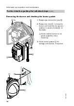
Page 16: ...er and checking the burner gasket 1 Release gas connection pipe B 2 Release six nuts C remove the burner and hook into the service position in service holder D on the boiler Never rest the burner on its gauze assembly wire mesh E 3 Check burner gasket F for damage and replace if required 5692 500 GB 6x E C A B D F E ...

Page 17: ... ignition and ionisation electrodes A 2 Turn thermal insulation ring B clockwise and remove carefully 3 Slacken eight Torx screws C and remove burner gauze assembly D and assembly gasket E 4 Insert a new burner gauze assembly D with new assembly gasket E and secure with eight Torx screws Torque 4 5 Nm 5 Refit thermal insulation ring B and ignition and ionisation electrodes A 5692 500 GB B A C A D ...

Page 18: ...trodes with a small brush or emery paper Ensure that the wire mesh is not damaged 3 Check all clearances If the gaps are not as specified or the electrodes are damaged replace and align the electrodes together with new gaskets Tighten the fixing screws with 2 Nm Disconnecting the neutralising system if installed and connecting a drain hose 1 Separate the hose to the neutralising system from siphon...

Page 19: ...se observe the following Only use solvent free cleaning agents Ensure that no solvent enters between the boiler body and the thermal insulation Remove soot deposits with alkaline agents containing surfactants e g Fauch 600 1 Safety instructions Observe the cleaning agent manufacturer s details Wear goggles protective gloves and protective clothing if necessary Combustion residues may create thin y...

Page 20: ... condensate drain system 1 Release fitting A on siphon B remove siphon B from the boiler 2 Clean the inside of the inlet connector C with a brush 3 Remove clean and refit base D of siphon B 4 Fill siphon B with water and secure on inlet connector C Safety instructions There is a risk of flue gas escaping if the siphon is not filled with water 5 If installed Maintain the neutralising system Neutral...

Page 21: ...on chamber with water Water must be able to flow without backpressure via the condensate drain system Otherwise clean the complete condensate drain system again Observe the neutralising system manufacturer s instructions Checking gaskets packing cords and thermal insulation 1 Check gaskets and packing cords 2 Check the thermal insulation of the burner 3 Replace all faulty parts 4 Check the thermal...

Page 22: ...r control unit Checking all gas equipment for leaks at operating pressure Safety instructions Carry out a leak test 1 Insert new gaskets in all fittings that have been opened 2 Open the gas shut off valve 3 Check all joints for leaks 4 Start up the burner Checking the mixer if installed for ease of operation and leaks 1 Remove the motorised lever from the mixer handle 2 Check the mixer for ease of...

Page 23: ...ons as well as all fault and error messages The display is composed of three elements comprising seven segments each Four keys are used for setting at the various operating levels A DIP switch on the rear of the display and programming unit enables burner parameters to be configured for settings see page 27 A Reset button B Decimal point will be set if a display value exceeds 99 C Cylinder LED wil...

Page 24: ...ondition Message code see table below Operating parameter display Below Service display Message code Operating parameter display Page 26 Fault display Display flashes Fault code Page 31 to 34 Display status Operating condition 0 No heat demand 1 System tests Heat demand 2 Fan run up 3 Pre purge 4 Pre ignition 5 Safety time 7 Mode 8 Post purge Display status Message code A Jumper B 3 missing see pa...

Page 25: ...state The service display shows FL if a flame is established 5692 500 GB reset button Press System tests Heat demand Pre purge Pre ignition Safety time Mode Post purge Standby Air pressure monitor Standby position Status Service Status Service Status Service Status Service Status Service Status Service Status Service Status Service Idle state check Fan run up Status Service ...

Page 26: ...s the lower rated output and d 00 with a decimal point behind the last figure represents the upper rated output 1 Press keys b and S simultaneously the burner changes over into manual mode Below status the display shows d 2 Set the lower rated output Press key b until the display shows d 00 3 Set the upper rated output Press key a until the display shows d 00 4 Press keys b and S simultaneously th...

Page 27: ... after replacing the burner control unit see page 28 27 kW parameter set 10 35 kW parameter set 11 49 kW parameter set 12 66 kW parameter set 13 Displaying the selected parameter set 1 Press keys b and S simultaneously Under status the following is shown in the display 1 2 Press S until the display shows 2 under status The two digit display below service indicates the selected parameter set 3 Pres...

Page 28: ...rvice indicate the selected parameter set see page 27 u is shown under service if an invalid DIP switch setting has been selected 1 Check DIP setting If required change in accordance with page 27 2 Press b and a simultaneously for approx 2 s The selected parameter settings have been accepted when p no longer flashes and the cylinder LED is illuminated 3 Press reset then the operating display will ...

Page 29: ...yed The light segments of the display will flash 5692 500 GB Operating phase in which fault occurred will be displayed for as long as key a is held down see flow chart on page 36 Additional error info will be displayed as long as key b is held down Automatic activation in case of fault state Operating display Status Service Status Service Status Service Fault code Operating display ...

Page 30: ...lt display will be activated from the operating display The fault memory display will be terminated if no key is pressed within 20 seconds 1 Simultaneously press reset and a this displays the most recent fault 2 Five more saved faults can be called up by pressing S 3 After displaying the oldest 6th fault return to the operating display by pressing S 5692 500 GB Status Service Status Service ...

Page 31: ... signal air pressure Air pressure switch connection leaks sealing washers faulty Check sealing washers and replace if necessary Excessive pressure drop on flue gas side Remove any condensate and clean flue gas system if required Fan does not run Fan faulty cables faulty or broken Check cables and replace fan if required 22 Burner does not start Jumper B 3 contact at slot aYA broken missing or faul...

Page 32: ...type selected Adjust gas type see page 9 Gas train does not open Check and replace combination valve if necessary Ionisation cable or electrode short circuited Straighten bent electrodes or remove contamination remove short circuit from the cable 26 Ionisation flame monitor signals l li h d i Ignition cables short circuited Remedy short circuit o o s g a s external light during start up or post pu...

Page 33: ...t 2b Internal fault flame monitor 2C Fault during test of safety inputs 2d Internal fault low voltage monitor 2E Internal fault voltage failure monitor 2F Internal fault heat demand 4E Internal error 31 Error in feedback from gas safety valves output relay does not activate 32 Error in feedback from auxiliary start up valve output relay does not activate 35 Error in feedback from ignition output r...

Page 34: ...tart up position no start up in spite of heat demand Jumper B 2 missing or broken Check jumper B 2 see page 40 A Burner control unit in fault state Jumper B 3 missing or broken Check jumper B 3 see page 40 L Air pressure switch shuts down during operation Flue gas backed up flue gas collector or system contaminated Remove flue gas blockage clean flue gas collector and flue system if necessary Inte...

Page 35: ...trol unit mains supply interchanged Check mains supply and swap cores CO is formed or burner is very sooty Too little or too much air Correct setting Open flue operation Check boiler room ventilation Balanced flue operation Check combustion air supply CO2 content too low Incorrect adjustment and or balanced flue system leak Adjust nozzle pressure in accordance with type of gas used Check whether b...

Page 36: ... GB Phase Temperature controller Fan Ign position Fan relay Air pressure monitor Safety valve Y1 Ignition Flame signal Safety temperature cut out Input Input Output Output Input Output Output Input 01 02 03 04 05 06 07 08 09 10 11 12 13 17 18 20 01 19 21 Error ON OFF ON or OFF ...

Page 37: ...unit will enter a fault state if the fan does not reach its set speed 08 Pre ignition 2 s 09 Start up safety time safety time A 2 8 s enable safety valves at the start of safety time A safety time operation 1 s 10 Flame stabilisation in ignition position 20 s 11 Changeover to control operation 1 to 30 s ramp up to the set speed programmed in the controller 12 Operation max 23 59 h the system will ...

Page 38: ...38 Burner Component summary 5692 500 GB M A B C D E L K H G F M H F N G O K ...

Page 39: ...ion electrodes C Fan D Ignition unit E Inlet flange F Flexible gas pipe G Ionisation electrode H Display and programming unit K Burner control unit L Gas combination valve M Air pressure switch N Thermal insulation ring O Burner gauze assembly 5692 500 GB ...

Page 40: ...on and feedback S 1 ON OFF switch S 2 Thermostat S 3 Output control T 1 Ignition transformer Y 1 Gas safety valve 5692 500 GB 31 COM 30 NO 29 COM 28 PE 27 NO 26 COM 25 PE 24 NO 23 COM 22 PE 21 NO 20 19 18 17 N 16 PE 15 Ign 14 N 13 PE 12 Fan 11 N 10 PE 9 Y2 8 N 7 PE 6 Y1 5 4 3 2 1 131 111 47 54 100 38 35 1 2 3 4 ION 5 UH 6 PWM 7 Spd 8 GND 9 B5 T6 T7 T8 PE L1 N T1 T2 S3 B4 41 90 100A 11 PE Y1 M1 M T...

Page 41: ...adaptor 137 Gas connection hose with gasket 138 Set of small burner parts 139 Adaptor air pressure switch with gaskets 200 Top plate 201 Side panel l h and r h side 202 Front panel 203 Rear panel 204 Insulating casing 205 Front insulating mat 206 Rear insulating mat 208 Vitocrossal 300 inscription 209 Edge protector 210 Decorative cap 211 Insulation pack fixing components 212 Vitotronic 100 mounti...

Page 42: ...42 Parts list Parts list cont 5692 500 GB 201 205 213 1 212 1 202 208 209 210 A B C ...

Page 43: ...43 Parts list Parts list cont 5692 500 GB 206 203 209 204 211 211 211 211 211 211 201 200 ...

Page 44: ...44 Parts list Parts list cont 5692 500 GB D 135 105 118 119 117 100 101 116 120 136 134 106 110 210 122 121 138 137 139 124 125 123 131 115 114 125 ...

Page 45: ...45 Parts list Parts list cont 5692 500 GB 003 003 008 009 005 008 001 002 007 004 006 ...

Page 46: ...ent CO2 H at lower rated output by vol H at higher rated output by vol Oxygen content O2 H at lower rated output by vol H at higher rated output by vol Carbon monoxide content CO H at lower rated output ppm H at higher rated output ppm Ionisation current H at lower rated output mA min 3 mA H at higher rated output mA min 10 mA Flue gas temperature at upper rated output ºC Draught Pa max 50 Pa Air ...

Page 47: ...47 Appendix Maint service Maint service Maint service Maint service 5692 500 GB ...

Page 48: ...tent CO2 H at lower rated output by vol H at higher rated output by vol Oxygen content O2 H at lower rated output by vol H at higher rated output by vol Carbon monoxide content CO H at lower rated output ppm H at higher rated output ppm Ionisation current H at lower rated output mA min 3 mA H at higher rated output mA min 10 mA Flue gas temperature at upper rated output ºC Draught Pa max 50 Pa Air...

Page 49: ...49 Appendix Maint service Maint service Maint service Maint service 5692 500 GB ...

Page 50: ...tent CO2 H at lower rated output by vol H at higher rated output by vol Oxygen content O2 H at lower rated output by vol H at higher rated output by vol Carbon monoxide content CO H at lower rated output ppm H at higher rated output ppm Ionisation current H at lower rated output mA min 3 mA H at higher rated output mA min 10 mA Flue gas temperature at upper rated output ºC Draught Pa max 50 Pa Air...

Page 51: ...51 Appendix Maint service Maint service Maint service Maint service 5692 500 GB ...

Page 52: ...at partial load Flue gas losses Available draught at the flue outlet 2 ºC ºC ºC kg h kg h Pa mbar Pa mbar 55 43 75 41 14 80 0 8 50 0 5 55 43 75 54 18 80 0 8 50 0 5 55 43 75 75 25 80 0 8 50 0 5 55 43 75 102 34 80 0 8 50 0 5 Product characteristics to EnEV Efficiency η at 100 of rated output 30 of rated output 96 8 106 4 96 6 105 9 96 9 106 3 97 1 106 2 Standby losses qB 70 1 2 0 8 0 7 0 5 Power con...

Page 53: ...0 50 50 Power consumption W 45 49 74 102 Fan speed at rated output min 1 4 256 4 480 5 056 5 952 Gas throughput subject to the operational net calorific value HuB Natural Net calorific Rated boiler output gas group value HuB 27kW 35kW 49kW 66 kW kWh m3 MJ m3 m3 h l min m3 h l min m3 h l min m3 h l min E 9 45 34 02 2 6 43 3 3 5 60 0 4 8 85 0 6 6 110 0 LL 8 13 29 25 3 1 51 6 4 1 70 0 5 6 98 3 7 7 12...

Page 54: ...3 EEC 89 336 EEC 90 396 EEC 92 42 EEC as follows _ 0085 BN 0570 This product meets the requirements of the Efficiency Directive 92 42 EEC for Condensing boilers The product characteristics determined as system values for Vitocrossal 300 as part of EC type testing according to the Efficiency Directive see specification table can be utilised for the energy assessment of heating and ventilation equip...

Page 55: ...ssmann Werke GmbH Co KG D 35107 Allendorf confirm that the following product meets the NOx limits specified by the 1st BImSchV 7 2 Vitocrossal 300 type CU3 incl MatriX radiant burner Allendorf 1 December 2002 Viessmann Werke GmbH Co KG pp Manfred Sommer 5692 500 GB ...

Page 56: ...displays 31 F Fault displays 31 Flow diagram 36 Function flow diagram 36 Function display 24 Function description 23 G Gas combination valve 10 Gas restrictors 9 Gas supply pressure 11 Gas type 9 Gas type checking 9 H Heating surfaces cleaning 19 I Ignition 37 Ignition and ionisation electrodes 18 Initial start up 4 Ionisation current 14 Ionisation current checking 14 M Maintenance 4 Manufacturer ...

Reviews: