13
Initial start−up, inspection and maintenance
Further details regarding the individual steps
(cont.)
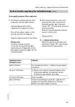
Checking the gas valve control pressure
1.
Start up the boiler.
2.
Operate the boiler at the higher
rated output (see page26).
3.
Remove the caps from test
nipples
A
of the gas combination
valve.
4.
Connect the gauge to both test
nipples
A
.
The differential pressure should
be 4.0mbar (400Pa).
If the actual value deviates by
more than
"
0.4mbar (40Pa)
H
Check the settings of the DIP
switches (see page27)
H
Check the flue gas and
ventilation air lines
H
Check pressure limiter
B
for
soundness (sealing washers).
Please note:
Use suitable test equipment with a
range from 0 to 1000Pa.
Vacuum pressure is applied to
both test nipples. The vacuum
pressure at the test nipple with the
"+" symbol is lower, and that at
the test nipple with the ""
symbol is higher.
Connect the pressure gauge
accordingly.
5.
Record the actual values in the
service report from page46.
Checking the draught
1.
Check the draught in Pa
(1Pa=0.01mbar) at connection
A
(flue gas, see page12) of the
boiler adaptor.
2.
Record the actual values in the
service report from page46.
5692500GB
A
B
Summary of Contents for CU3
Page 38: ...38 Burner Component summary 5692 500 GB M A B C D E L K H G F M H F N G O K ...
Page 42: ...42 Parts list Parts list cont 5692 500 GB 201 205 213 1 212 1 202 208 209 210 A B C ...
Page 43: ...43 Parts list Parts list cont 5692 500 GB 206 203 209 204 211 211 211 211 211 211 201 200 ...
Page 45: ...45 Parts list Parts list cont 5692 500 GB 003 003 008 009 005 008 001 002 007 004 006 ...
Page 47: ...47 Appendix Maint service Maint service Maint service Maint service 5692 500 GB ...
Page 49: ...49 Appendix Maint service Maint service Maint service Maint service 5692 500 GB ...
Page 51: ...51 Appendix Maint service Maint service Maint service Maint service 5692 500 GB ...


