VE272SFS Roll Grooving Tool
19
4.
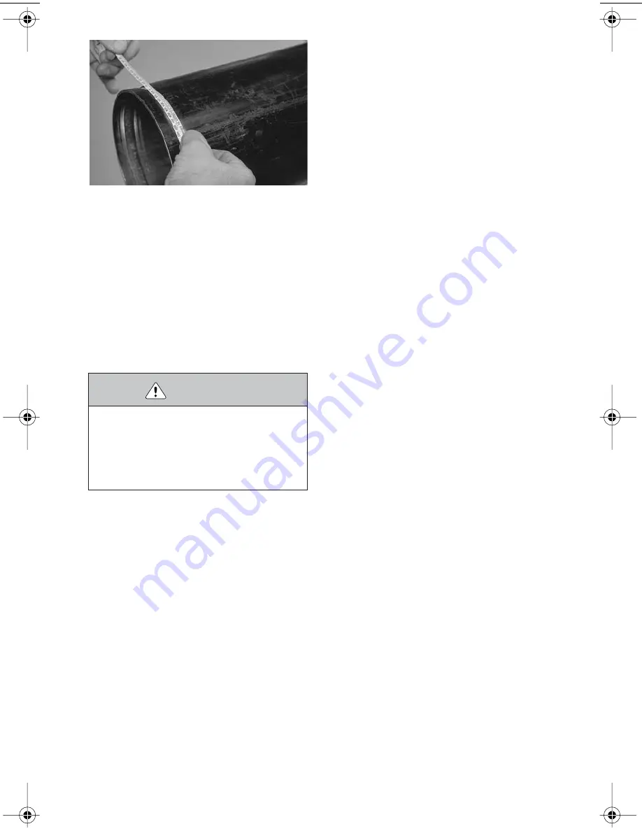
After a trial groove is prepared and the
pipe/tubing is removed from the tool, carefully
check the groove diameter (“C” dimension).
Refer to the "Roll Groove Specifications" sec-
tion, starting on page 45. The PT-100 Pipe
Tape, supplied with the tool, is the best meth-
od for checking the “C” dimension. In addi-
tion, a vernier caliper or narrow-land
micrometer can be used to check this dimen-
sion at two locations (90º apart) around the
groove. The average reading must be within
the required groove diameter specification.
5.
If the groove diameter (“C” dimension) is
not within Victaulic specifications, the diame-
ter stop must be adjusted.
5a.
To adjust for a smaller groove diameter,
turn the depth adjuster
counterclockwise
(when viewed from above the tool).
5b.
To adjust for a larger groove diameter,
turn the depth adjuster
clockwise
(when
viewed from above the tool).
NOTE:
A quarter-turn either way will change
the groove diameter adjustment by approxi-
mately 0.031 inch (0,8 mm) or 0.125 inch (3,2
mm) per full turn.
6.
Prepare another trial groove, and check
the groove diameter (“C” dimension), as
described in step 4. Repeat these steps, as
necessary, until the groove diameter is within
specification.
CAUTION
• The “C” dimension (groove diameter) must conform
to Victaulic specifications to ensure proper joint
performance.
Failure to follow this instruction could cause joint
failure, resulting in personal injury and/or property
damage.
TM-VE272SFS 3776 Rev_B.fm Page 19 Friday, December 3, 2004 12:10 PM
Summary of Contents for VE272SFS
Page 2: ......


