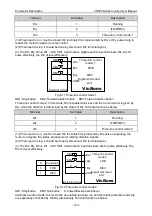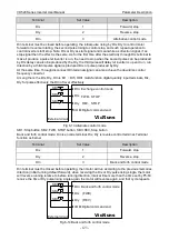
VD520 Series Inverter User Manual Parameter Description
- 131 -
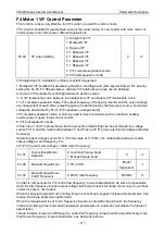
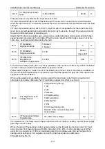
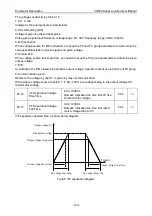
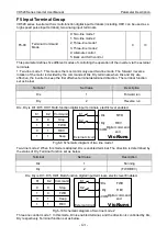
F6 Output Terminal Function Group
F6-00
HDO1 Terminals Output
Mode Selection
0: HS Pulse output
1: Switch signal output
0
○
HDO1 terminal is programmable multiplexing terminal. It can be used as high-speed pulse output
terminal, it can also be used as collector open circuit output terminal.
When as a pulse output, the highest frequency of the output pulse is 100kHz, related functions refer
to the instruction of F6-12.
F6-01
HDO1 Terminals Output
Function Mode Selection
0~41, see table blow
0
○
F6-02
Relay T1 Function
Selection
0
○
F6-03
Relay T2 Function
Selection
0
○
F6-04
DO1 Output Terminal
Function Selection
0
○
Digit output terminal function table:
Set
Value
Function
Description
0
No output
Output terminals without any function.
1
Inverter in running
It indicate the inverter is in running state, have the output
frequency( can be zero), output ON signal at this time.
2
Ready for run
When the inverter main circuit and control loop is stable, and the
inverter is not detected any fault information, and the inverter is in
the running sate, output ON signal.
3
Fault output 1
(continue running
without output)
When the inverter is failure (except when the fault protection
action is continue operation), output ON signal.
4
Fault output 2 (don’t
output undervoltage)
When the inverter is failure (except when undervoltage or fault
protection action is continue operation), output ON signal.
5
Warning output
(output when fault)
When the inverter is failure, output ON signal.
6
Output undervoltage
When the inverter is in undervoltage condition, output ON signal.
7
Frequency level
detection FDT1
output
Please refer to the instruction of function code Fb-16, Fb-17.
8
Frequency level
detection FDT2
output
Please refer to the instruction of function code Fb-18, Fb-19.
9
Frequency reached
Please refer to the instruction of function code Fb-20.
10
Frequency 1 reached
output
Please refer to the instruction of function code Fb-21, Fb-22.

