Function Parameter Table VD520 Series Inverter User Manual
- 82 -
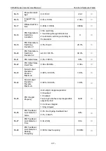
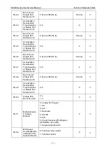
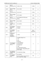
A0-17
Rotational
Inertia
Compensation
Coefficient
0.00~10.00
0.00
○
A0-18
Rotational
Inertia
Compensation
Upper Limit
0.0%~50.0%
5.0%
○
A0-19
Rotational
Inertia
Compensation
Starting
Frequency
0.00Hz~max frequency
10.00Hz
○
A0-20
Lowest
Resolution
Frequency (only
effective to
SVC)
0.00: Not limit
0.01Hz~2.00Hz
1.00Hz
○
A0-21
Disconnection
Detection
Time
0.0: Disconnection is invalid
0.1~60.0s
0.0
○
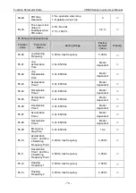
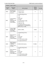
A1 Optimize Control Parameter
Function
Code
Parameter
Name
Setting Range
Factory
Default
Value
Property
A1-00
Carrier
Frequency
0.5kHz~16.0kHz
Model
dependent
○
A1-01
Carrier
Frequency
Adjustment with
the Temperature
0: No
1: Yes
1
○
A1-02
DPWM
Switching
Frequency
Upper Limit
0.00Hz~15.00Hz
12.00Hz
○
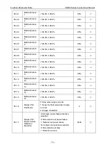
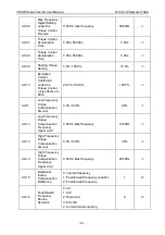
A1-03
PWM
Modulation
Mode
LED unit
’s digit:
0: Asynchronous modulation
1: Synchronous modulation
LED ten
’s digit:
0: Two phase and three phase
modulation
1: Three phase modulation
0x00
◎
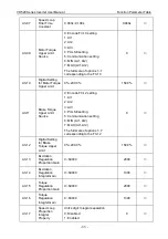
A1-04
Dead Zone
Compensation
Mode Selection
0: Without compensation
1: Compensation 1
2: Compensation 2
1
○


