Parameter Description VD520 Series Inverter User Manual
- 128 -
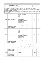
F5-17
DI2 Open Delay Time
0.0s~3600.0s
0.0s
◎
F5-18
DI3 Open Delay Time
0.0s~3600.0s
0.0s
◎
Is used to set DI terminal state changes, delay time of the frequency inverter for the change.
Only DI1, DI2, DI3 have the function that set the delay time at present.
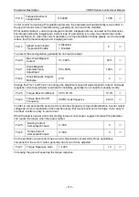
F5-19
Terminal UP/DOWN
change rate
0.001Hz/s~65.535Hz/s
1.000Hz/s
○
Used to set the terminal UP/DOWN to adjust the setting frequency, the speed of frequency change,
that is the frequency variation per second.
When F0-15 (frequency decimal point) is 2, the value range is from 0.001Hz/s to 65.535Hz/s.
When F0-15 (frequency decimal point) is 1, the value range is from 0.01Hz/s to 655.35Hz/s
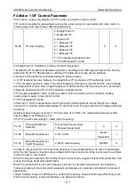
F5-20
AI Curve Selection
Unit’s digit: AI1 curve selection
1: Curve 1 (2 point, see F5-22~F5-26)
2: Curve 2 (2 point, see F5-27~F5-31)
3: Curve 3 (2 point, see F5-32~F5-36)
4: Curve 4 (4 point, see b2~00-b2-07)
5: Curve 5 (4 point, see b2-08~b2-15)
Ten’s digit: AI2 curve selection, same as
above
Hundred’s digit: reserved
0x321
○
The
unit’s digit and ten’s digit of function code are used to select respectively, the analog input AI1,
AI2 corresponding set curve, each analog input can choose any one of 5 kinds of curves.
Curve 1, 2, 3 are 2 point curve, set in the F5 group function code, and the curve 4 and 5 are 4 points,
need to set in the function code in group b2.
VD520 inverter standard unit provides 2 way analog input port.
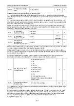
F5-21
AI is Lower than Min
Input Set Selection
Unit’s digit: AI1 is lower than min input
setting selection
0: Corresponding to the min input set
1: 0.0%
Ten’s digit: AI2 is lower than min input
setting selection, same as above
Hundred’s digit: reserved
0X000
○
The function code is used for setting, when the voltage of the analog input is smaller than the
“minimum input” set, how to determine the setting of analog corresponds.
The unit’s digit and ten’s digit of function code are corresponding analog input AI1, AI2 respectively.
If selection is 0, when the
AI input is lower than the “minimum input”, then the analog corresponding
setting
for “minimum input corresponding setting” of function code to determine the curve (F5-27,
F5-22).
If selection is 1, when the AI input is lower than the minimum input, then the analog corresponding
setting is set to 0.0%.
F5-22
AI Curve 1 Min Input
-10V~F5-24
0.00V
○
F5-23
Corresponding Setting of
AI Curve 1 Min Input
-100.0%~+100.0%
0.0%
○
F5-24
AI Curve 1 Max Input
F5-22~+10.00V
10.00V
○


