Function Parameter Table VD520 Series Inverter User Manual
- 90 -
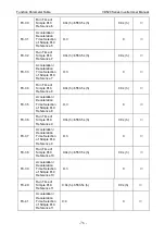
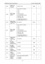
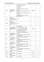
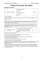
b1-06
Virtual VDI
Terminal state
setting
Unit’s digit: virtual VDI1
0: Disabled
1: Enabled
Ten’s digit: virtual VDI2, same as
above
Hundred’s digit: virtual VDI3, same as
above
Thousand’s digit: virtual VDI4, same
as above
Ten thousand’s digit: virtual VDI5,
same as above
0x00000
◎
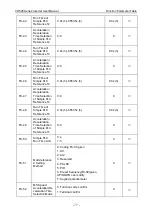
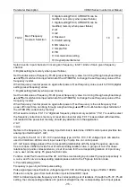
b1-07
Function
Selection when
AI1 Terminal as
DI
0~59
0
◎
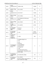
b1-08
Function
Selection when
AI2 Terminal as
DI
0~59
0
◎
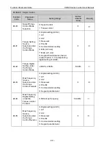
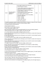
b1-10
Effective Mode
Selection when
AI1 Terminal as
DI
Unit’s digit: AI1
0: High electrical level enable
1: Low electrical level enable
Ten’s digit: AI2, same as above
Hundred’s digit: reserved
0x000
◎
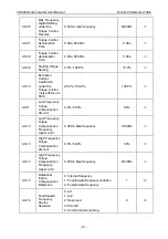
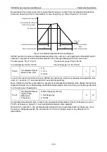
b1-11
Virtual VDO1
Output Function
Selection
0: Short circuit with physical DIX
internal
1~43: see the F6 group physical DO
output selection
0
○
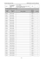
b1-12
Virtual VDO2
Output Function
Selection
0: Short circuit with physical DIX
internal
1~43: see the F6 group physical DO
output selection
0
○
b1-13
Virtual VDO3
Output Function
Selection
0: Short circuit with physical DIX
internal
1~43: see the F6 group physical DO
output selection
0
○
b1-14
Virtual VDO4
Output Function
Selection
0: Short circuit with physical DIX
internal
1~43: see the F6 group physical DO
output selection
0
○
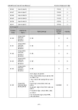
b1-16
VDO1 Closing
Delay
0.0s~3600.0s
0.0s
○
b1-17
VDO2 Closing
Delay
0.0s~3600.0s
0.0s
○
b1-18
VDO3 Closing
Delay
0.0s~3600.0s
0.0s
○

