VD520 Series Inverter User Manual Parameter Description
- 115 -
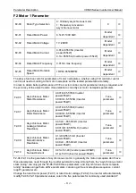
F3-07
Speed Loop Filter Time
Constant
0.000s~0.100s
0.000s
○
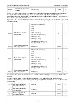
Under the vector control mode, the output of the speed loop controller for torque current instruction,
the parameter is used for filtering for torque instruction. Generally do not need to adjust the
parameters, it can be appropriately increase the filtering time when speed is volatile; if motor volatility,
this parameters should be reduced.
Speed loop filter time constant is small, the inverter output torque may be volatile, but the response of
the speed is fast.
F3-09
Motor Torque Upper
Limit Source
0: Encode F3-10 setting
1: AI1
2: AI2
3: AI3
4: PULSE setting
5: Communication setting
6: MIN (AI1, AI2)
7: MAX (AI1, AI2)
The full scale of options 1~7
corresponding to the F3-10
0
○
F3-10
Digital Setting for Motor
Torque Upper Limit
0%~200.0%
150.0%
○
F3-11
Brake Torque Upper
Limit Source
0: Encode F3-12 setting
1: AI1
2: AI2
3: AI3
4: PULSE setting
5: Communication setting
6: MIN (AI1, AI2)
7: MAX (AI1, AI2)
The full scale of options 1~7
corresponding to the F3-12
0
○
F3-12
Digital Setting for Brake
Torque Upper Limit
0%~200.0%
150.0%
○
In speed control mode, the maximum value of the inverter output torque, by the torque limit source
control.
F3-09 is used to select the set source of torque upper limit, when setting by analog, PULSE,
communication, 100% of corresponding set corresponding F3-10, and 100% of F3-10 is the inverter
rated torque.
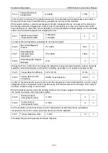
F3-13
Excitation Adjustment
Proportional Gain
0~60000
2000
○
F3.14
Excitation Adjustment
Integral Gain
0 ~60000
1300
○
F3-15
Torque Adjustment
Proportional Gain
0~60000
2000
○


