Vezco VZ-NVR-161080-P Quick Start Manual Download Page 21

Network Video Recorder User Manual 


Control PTZ camera movement in PTZ control mode 
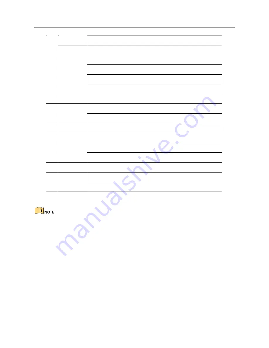


ENTER 

Confirm selection in any menu mode 

Checks checkbox 

Play or pause video in Playback mode 

Advance video a single frame in single-frame Playback mode 

Stop/start auto switch in auto-switch mode 

13 

PTZ 

Enter PTZ Control mode 


14 


ESC 

Go back to previous screen 

N/A 

15 

RESERVED 

Reserved 


16 


F1 

Select all items on a list 

N/A 

Switch between play and reverse play in Playback mode 

17 

PTZ Control 

Adjust PTZ camera iris, focus, and zoom 


18 


F2 

Cycle through tab pages 

Switch between channels in Synchronous Playback mode 


Troubleshooting Remote Control: 


Make sure you have installed batteries properly in the remote control. And you have to 
aim the remote control at the IR receiver in the front panel. 

If there is no response after you press any button on the remote, follow the procedure 
below to troubleshoot. 

Step 1 Go to Menu > Settings > General > More Settings by operating the front control 

panel or the mouse. 

Step 2 Check and remember NVR ID#. The default ID# is 255. This ID# is valid for all the 

IR remote controls. 

Step 3 Press the DEV button on the remote 

control. Step 4 Enter the NVR ID# you set in 

step 2. 

Step 5 Press the ENTER button on the remote. 

Summary of Contents for VZ-NVR-161080-P

Page 1: ...NETWORK VIDEO RECORDER Quick Start Guide...

Page 2: ...LOSS OF BUSINESS PROFITS BUSINESS INTERRUPTION OR LOSS OF DATA OR DOCUMENTATION IN CONNECTION WITH THE USE OF THIS PRODUCT EVEN IF OUR COMPANY HAS BEEN ADVISED OF THE POSSIBILITY OF SUCH DAMAGES REGAR...

Page 3: ...nce 2 This device must accept any interference received including interference that may cause undesired operation EU Conformity Statement This product and if applicable the supplied accessories too ar...

Page 4: ...mbols that may be found in this document are defined as follows Symbol Description Provides additional information to emphasize or supplement important points of the main text Indicates a potentially...

Page 5: ...he device turn off the power at once and unplug the power cable and then please contact the service center Preventive and Cautionary Tips Before connecting and operating your device please be advised...

Page 6: ...ion and VGA video output at up to 2K resolution Multiple screen display in live view is supported and the display sequence of channels is adjustable Live view screen can be switched in group Manual sw...

Page 7: ...e etc Smart search for the selected area in thevideo Zooming in when playback Reverse playback of multi channel Supports pause play reverse speed up speed down skip forward and skip backward when play...

Page 8: ...work interface for VZ NVR 81080 P VZ NVR 161080 P VZ NVR3200 4HD P VZ NVR3200 4HD Eight independent PoE network interfaces for the VZ NVR 81080 P models and sixteen independent PoE network interfaces...

Page 9: ...o the remote host Remotely start stop recording Remotely start stop alarm output Remote PTZ control Remote JPEG capture Virtual host function is provided to get access and manage the IP camera directl...

Page 10: ...iguration 34 2 3 Adding and Connecting the IP Cameras 39 2 3 1 Activating the IP Camera 39 2 3 2 Adding the Online IP Cameras 40 2 3 3 Editing the Connected IP Cameras and Configuring Customized Proto...

Page 11: ...and Capture 94 5 10 Files Protection 95 5 10 1 Locking the Recording Files 95 5 10 2 Setting HDD Property to Read only 97 Chapter 6 Playback 99 6 1 Playing Back Record Files 99 6 1 1 Instant Playback...

Page 12: ...figuring POS Privacy Information Filtering 170 9 4 Configuring POS Alarm 170 Chapter 10 VCA Alarm 173 10 1 Face Detection 173 10 2 Vehicle Detection 175 10 3 Line Crossing Detection 176 10 4 Intrusion...

Page 13: ...Network HDD 201 13 3 Managing eSATA 203 13 4 Managing HDD Group 234 13 4 1 Setting HDD Groups 234 13 4 2 Setting HDD Property 234 13 5 Setting HDD Property 234 13 6 Configuring Disk Clone 234 13 7 Che...

Page 14: ...Restoring Default Settings 234 16 2 Restoring Default Settings 234 16 3 Restoring Default Settings 234 16 4 Configuring More Settings 234 16 5 Managing User Accounts 234 Chapter 17 Appendix 269 17 1...

Page 15: ...fields and ON OFF switch In playback mode it can be used to play or pause the video In single frame play mode pressing the Enter button will play the video by a single frame In auto sequence view mode...

Page 16: ...e Universal Serial Bus USB ports for additional devices such as USB mouse and USB Hard Disk Drive HDD 1 1 2VZ NVR 81080 P VZ NVR 161080 P Figure 1 2 VZ NVR 81080 P VZ NVR 161080 P Table 1 2 Panel Desc...

Page 17: ...VRs You may also pair an IR Remote to a specific NVR by changing the Device ID as follows Pairing Enabling the IR Remote to a Specific DVR optional You can pair an IR Remote to a specific private DVR...

Page 18: ...VR functions proceed as follows Press the DEV key on the IR Remote Any existing Device ID will be erased from the unit s memory and it will no longer function with the DVR Re enabling the IR Remote re...

Page 19: ...ght desired selection 3 Press Enter button 12 to accept selection If User Is Not Logged On 1 Hold Power On Off button 1 down for five seconds to display the user name password prompt 2 Press the Enter...

Page 20: ...e PTZ Control menu Switch on screen keyboards upper and lower case alphabet symbols and numerals 6 REC Enter Manual Record setting menu Call a PTZ preset by using the numeric buttons in PTZ control se...

Page 21: ...om 18 F2 Cycle through tab pages Switch between channels in Synchronous Playback mode Troubleshooting Remote Control Make sure you have installed batteries properly in the remote control And you have...

Page 22: ...there is still no response from the remote please check the following Batteries are installed correctly and the polarities of the batteries are not reversed Batteries are fresh and not outof charge I...

Page 23: ...ovider The operation of the mouse Table 1 4 Description of the Mouse Control Name Action Description Left Click Single Click Live view Select channel and show the quick set menu Menu Select and enter...

Page 24: ...d 1 Figure 1 5 Soft Keyboard 2 Description of the buttons on the soft keyboard Table 1 5 Description of the Soft Keyboard Icons Icon Description Icon Description Number English letter Lowercase Upperc...

Page 25: ...eo output connector 5 ALARM IN Connector for alarm input ALARM OUT Connector for alarm output 6 LAN Network Interface 1 10 100 1000 Mbps self adaptive Ethernet interface 7 USB Interface Universal Seri...

Page 26: ...tor for audio output 3 LINE IN RCA connector for audio input 4 HDMI HDMI video output connector 5 USB 3 0 interface Universal Serial Bus USB ports for additional devices such as USB mouse and USB Hard...

Page 27: ...r User Manual 11 AC 100V 240V 100V to 240VAC power supply 12 Power Switch Switch for turning on off the device 13 Network Interfaces with PoE function Network interfaces for the cameras and to provide...

Page 28: ...S be used in conjunction with the device The Power indicator LED on the front panel should be red indicating the device gets the power supply Step 2 Press the POWER button on the front panel The Power...

Page 29: ...the NVR In the Shutdown menu you can also reboot the NVR Step 10 Enter the Shutdown menu by clicking Menu Shutdown Step 11 Click the Logout button to lock the NVR or the Reboot button to reboot the NV...

Page 30: ...n better protect your product Step 2 Click OK to save the password and activate the device Step 3 When the device is activated the system pops up the message box to remind you to remember the password...

Page 31: ...ttention Interface 2 1 3Using the Unlock Pattern for Login For the Admin user you can configure the unlock pattern for device login Configuring the Unlock Pattern Step 1 After the device is activated...

Page 32: ...4 dots to draw the pattern Each dot can be connected for once only Step 3 Draw the same pattern again to confirm it When the two patterns match the pattern is configured successfully Figure 2 8 Confi...

Page 33: ...unlock thedevice Please configure the pattern first before unlocking Please refer to Configuring the Unlock Pattern Step 1 Right click the mouse on the screen and select the menu to enter the interfa...

Page 34: ...s the system will switch to the normal login mode automatically Figure 2 11 Normal Login Dialog Box 2 1 4Login and Logout User Login Purpose If NVR has logged out you must login the device before oper...

Page 35: ...After you have logged out the system menu operation on the screen is invalid It is required to input a user name and password to unlock the system 2 1 5Resetting Your Password When you forget the pas...

Page 36: ...et the new admin password Refer to Chapter 2 1 2 Activating Your Device for details Step 4 Click OK to set the new password You can export the new GUID file to the U flash disk for future password res...

Page 37: ...that moment click the Cancel button You can also choose to use the Setup Wizard next time by leaving the Start wizard when the device starts checkbox checked Step 2 Click Next button to enter the date...

Page 38: ...1000M network interface for VZ NVR3200 4HD P Step 4 Click Next button after you configured the basic network parameters Then you will enter the Cloud P2P interface Configure the Cloud P2P according to...

Page 39: ...Parameters Step 7 Click Next button to enter the Array Management window Figure 2 20 Array Management Step 8 Click Next button after you configured the network parameters which takes you to the HDD Ma...

Page 40: ...n active status If the camera is in inactive status you can click the inactive icon of the camera to set the password to activate it You can also select multiple cameras from the list and click the On...

Page 41: ...ick menu in live view mode or click Menu Camera Camera to enter the IP camera management interface For the IP camera detected online in the same network segment the Password status shows whether it is...

Page 42: ...ters in order to increase the security of your product And we recommend you reset your password regularly especially in the high security system resetting the password monthly or weekly can better pro...

Page 43: ...the Add button to add it directly and you can click the Search button to refresh the online IP camera manually Figure 2 27 Quick Adding IP Camera Interface Or you can choose to custom add the IP camer...

Page 44: ...and click the button to add the camera Or you can click the One touch Adding button to add all cameras with the same login password from the list Make sure the camera to add has already been activate...

Page 45: ...ivated you can activate it from the IP camera list on the camera management interface Step 3 Optional Check the checkbox of Continue to Add to add other IP cameras Step 4 Click Add to add the camera T...

Page 46: ...ssword and risk password Figure 2 31 Security Level of IP Camera s Password Enabling the Password of IP Camera Visible For the admin login user account you can check the checkbox of Show Password of I...

Page 47: ...the icon to edit the parameters you can edit the IP address protocol and other parameters Figure 2 33 Edit the Parameters Channel Port If the connected device is an encoding device with multiple chann...

Page 48: ...figuration of the Camera Step 3 Click OK to save the settings and exit the interface Configuring the customized protocols Purpose To connect the network cameras which are not configured with the stand...

Page 49: ...eam The format of the URL is Type IP Address of the network camera Port Path Example rtsp 192 168 1 55 554 ch1 main av_stream Protocol Name Edit the name for the custom protocol Enable Substream If th...

Page 50: ...D P NVR The PoE interfaces enables the NVR system to pass electrical power safely along with data on Ethernet cabling to the connected network cameras If you disable the PoE interface you can also con...

Page 51: ...arameters of the camera can t be edited The IP address of the camera can only be edited in the Network Configuration interface see Chapter 11 1 Configuring General Settings for detailed information Fi...

Page 52: ...he long network cable mode Step 1 Enter the PoE Configuration interface Menu Camera Camera PoE Configuration Step 2 Click the radio button of each POE channel to switch and You can click the radio but...

Page 53: ...IP camera models When the transmission distance reaches 100 to 250 meters it must use the CAT5E or CAT6 network cable to connect with the PoE interface When the transmission distance reaches 250 to 3...

Page 54: ...pper right of the screen for each channel showing the status of the record and alarm in the channel so that you can know whether the channel is recorded or whether there are alarms occur as soon as po...

Page 55: ...continuous record and motion detection record aresupported Output Mode select the output mode to Standard Bright Gentle orVivid Add IP Camera the shortcut to the IP camera management interface Playba...

Page 56: ...Mouse Operation in Live View Name Description Common Menu Quick access to the sub menus which you frequently visit Menu Enter the main menu of the system by right clicking the mouse Single Screen Swit...

Page 57: ...g camera supports intelligent function the Reboot Intelligence option is included when right clicking mouse on this camera Figure 3 1 Right click Menu 3 2 3Using an Auxiliary Monitor Certain features...

Page 58: ...Icons Icon Description Icon Description Icon Description Enable Disabl e Manual Record Instant Playbac k Mute Audio on Capture PTZ Control Digital Zoom Image Settings Face Detectio n Live Vie w Strate...

Page 59: ...iew Strategy can be selected to set strategy including Real time Balanced Fluency Figure 3 5 Live View Strategy Face detection function can be used to detect the human faces in live view mode and save...

Page 60: ...demand 180 Panorama Switch the live view image to the 180 panoramaview 360 Panorama Switch the live view image to the 360 panoramaview PTZ Expansion The PTZ Expansion is the close up view of some defi...

Page 61: ...ude Video Output Interface Designates the output to configure the settings for HDMI and VGA video outputs Live View Mode Designates the display mode to be used for Live View Dwell Time The time in sec...

Page 62: ...l the live view 4 Click the Apply button to save the setting You can also click and drag the camera to the desired window on the live view interface to set the camera order Step 3 Set the stream type...

Page 63: ...lity channel zero encoding is supported as an option for you Step 1 Enter the Live View Settings interface Menu Configuration Live View Step 2 Select the Channel Zero Encoding tab Figure 3 10 Live Vie...

Page 64: ...the procedure to set the parameters for PTZ The configuring of the PTZ parameters should be done before you control the PTZ camera Step 1 Enter the PTZ Settings interface Menu Camera PTZ Figure 4 1 P...

Page 65: ...tep 3 Choose the camera for PTZ setting in the Camera dropdown list Step 4 Enter the parameters of the PTZ camera All the parameters should be exactly the same as the PTZ camera parameters Step 5 Clic...

Page 66: ...Control interface Menu Camera PTZ Figure 4 3 PTZ Settings Step 2 Use the directional button to wheel the camera to the location where you want to set preset and the zoom and focus operations can be re...

Page 67: ...ontrol panel Step 2 Choose Camera in the dropdown list Step 3 Click the button to show the general settings of the PTZ control Figure 4 4 PTZ Panel General Step 4 Click to enter the preset No in the c...

Page 68: ...ough the patrol The Duration refers to the time span to stay at the corresponding key point The Speed defines the speed at which the PTZ will move from one key point to the next Step 5 Click the Add b...

Page 69: ...Figure 4 7 PTZ Panel General Step 3 Select a patrol in the dropdown list and click the Call Patrol button to call it Step 4 You can click the Stop Patrol button to stop calling it 4 2 5Customizing Pa...

Page 70: ...ess the PTZ button on the front panel or click the PTZ Control icon in the quick setting bar or select the PTZ option in the right click menu to show the PTZ control panel Step 2 Click the button to s...

Page 71: ...ll the angle from the left limit to the right limit should be no more than 180 4 2 8Calling Linear Scan Before operating this function make sure the connected camera supports the linear scan and is in...

Page 72: ...nnected camera supports the linear scan and is in private protocol Purpose For some certain model of the speed dome it can be configured to start a predefined park action scan preset patrol and etc au...

Page 73: ...1 to preset 32 in order after the park time The undefined preset will be skipped Park Patrol 1 The dome starts move according to the predefined patrol 1 path after the park time Park Preset 1 The dome...

Page 74: ...TZ Control button on the front panel or on the remote control or choose the PTZ Control icon or select the PTZ option in the right click menu Click the Configuration button on the control panel and yo...

Page 75: ...uto cycle button Zoom Focus Iris Zoom Focus Iris The speed of the PTZ movement Light on off Wiper on off 3D Zoom Image Centralization Menu Switch to the PTZ control interface Switch to the one touch c...

Page 76: ...initialize it Menu HDD General Figure 5 1 HDD General 2 Check the storage mode of the HDD Click Advanced to check the storage mode of the HDD If the HDD mode is Quota please set the maximum record ca...

Page 77: ...coding to H 265 or H 264 Enable H 264 Mode check the checkbox to enable Once enabled the Max Bitrate Mode Max Bitrate Kbps and Max Bitrate Range Recommend are not configurable Enabling it helps to ens...

Page 78: ...apture you save the record and captured picture in the redundant HDD See Chapter Configuring Redundant Recording and Capture Record Audio Check the checkbox to enable or disable audio recording Video...

Page 79: ...ick Apply to save the settings Step 4 Parameters Settings for Capture 1 Select the Capture tab Figure 5 6 Capture Parameters 2 Configure the parameters 3 Click Apply to save the settings The interval...

Page 80: ...ed to configure schedule for both recording and capture To schedule the automatic capture you need to choose the Capture tab in the Schedule interface Step 1 Enter the Record Schedule interface Menu R...

Page 81: ...button or click on the color icon under the edit button and draw the schedule line on the panel Edit the schedule The all day continuous recording is configured for the device by factory default I In...

Page 82: ...ings or VCA settings as well For detailed information refer to Chapter 8 1 and Chapter 9 The VCA settings are only available to the smart IP cameras Repeat the above edit schedule steps to schedule re...

Page 83: ...I Click the Apply button to validate the settings Step 3 Optional If the settings can also be used to other channels click Copy and then choose the channel to which you want to copy Step 4 Click Apply...

Page 84: ...e surveillance center and so on In this chapter you can follow the steps to schedule a record which triggered by the detected motion Step 1 Enter the Motion Detection interface Menu Camera Motion Figu...

Page 85: ...motion detection event to triggerrecording 2 Click Apply to save the settings 3 Click OK to back to the upper level menu 4 Exit the Motion Detection menu Step 3 Edit the Motion Detection Record Sched...

Page 86: ...ording or capture Step 1 Enter the Alarm settings interface Menu Configuration Alarm Figure 5 14 Alarm Settings Step 2 Click Alarm Input Figure 5 15 Alarm Settings Alarm Input 1 Select Alarm Input num...

Page 87: ...er level menu Repeat the above steps to configure other alarm input parameters If the settings can also be applied to other alarm inputs click Copy and choose the alarm input number Figure 5 17 Copy A...

Page 88: ...unattended baggage detection object removal detection audio loss exception detection sudden change of sound intensity detection and defocus detection Step 1 Enter the VCA settings interface and selec...

Page 89: ...The PTZ Linking function is only available for the VCA settings of IP cameras Step 6 Enter Record Schedule settings interface Menu Record Schedule Record Schedule and then set VCA as the record type F...

Page 90: ...SHOT button on the front panel Figure 5 20 Manual Record Step 2 Enable the Manual Recording 1 Select Record on the left bar 2 Click the status button before camera number to change o Step 3 Disable ma...

Page 91: ...Network Video Recorder User Manual Green icon means that the channel is configured the capture schedule After rebooting all the continuous capture will be canceled...

Page 92: ...record or capture schedule on holiday for that year You may want to have different plan for recording and capture on holiday Step 1 Enter the Record setting interface Menu Record Holiday Figure 5 22 H...

Page 93: ...three different modes for the date format to configure holiday schedule 5 Set the start and end date 6 Click Apply to save settings 7 Click OK to exit the Edit interface Step 3 Enter Record Capture S...

Page 94: ...eral Step 2 Select the HDD and click to enter the Local HDD Settings interface 1 Set the HDD property to Redundancy Figure 5 25 HDD General Editing 2 Click Apply to save the settings 3 Click OK to bac...

Page 95: ...llowing interface Figure 5 26 Record Parameters 3 Select Camera you want to configure in the drop down list 4 Check the checkbox of Redundant Record Capture 5 Click OK to save settings and back to the...

Page 96: ...p 4 Click to enter editing interface Step 5 Configuring HDD group 1 Choose a group number for the HDD group 2 Click Apply and then in the pop up message box click Yes to save your settings 3 Click OK...

Page 97: ...ayback Step 2 Check the checkbox of channel s in the channel list and then double click to select a date on the calendar Figure 5 29 Normal Smart Playback Step 3 During playback click the button to lo...

Page 98: ...unlock the file and the file is not protected Lock File when Export Step 1 Enter Export setting interface Menu Export Figure 5 31 Export Step 2 Select the channels you want to search by checking the c...

Page 99: ...ot be locked 2 Click to change it to to unlock the file and the file is not protected Figure 5 33 Unlocking Attention 5 10 2 Setting HDD Property to Read only Step 1 Enter HDD setting interface Menu H...

Page 100: ...D If you want to save files in the HDD change the property to R W If there is only one HDD and is set to Read only the NVR can t record anyfiles Only live view mode is available If you set the HDD to...

Page 101: ...by channel Choose a channel in live view mode and click the button in the quick setting toolbar In the instant playback mode only record files recorded during the last five minutes on this channel wi...

Page 102: ...pecified time duration Multi channel simultaneous playback and channel switch are supported Step 2 Enter playback interface Menu Playback Step 3 Select the Normal Smart in the drop down list on the to...

Page 103: ...es blue for continuous recording and red for event recording Step 6 Click the radio button to start playing the continuous recorded files Playback Interface You can use the toolbar in the bottom part...

Page 104: ...ssing detection Draw quadrilateral for the intrusion detection Filter video files by setting the target characters Operations Audio on Mute Start Stop clipping Capture Picture Lock File Add default ta...

Page 105: ...mation When you select the smart playback mode the system will analyze the video containing the motion line or intrusion detection information mark it with green color and play it in the normal speed...

Page 106: ...e to specify the start point and end pointof the line Intrusion Detection Click the button and specify 4 points to set a quadrilateral region for intrusion detection Only one region can be set Motion...

Page 107: ...ted parameters Skip the Non Related Video check the checkbox to enable the device to skip non related video files Play Non Related Video set the playing speed to 8X 4X 2X 1X when playing the non relat...

Page 108: ...4 Select the major type to Alarm Input Motion POS or VCA as the event type We take playback by VCA as the example in the following instructions Figure 6 9 Event Search Interface Step 5 Select the mino...

Page 109: ...nfigured Step 9 Optional Enter the Synch Playback interface to select the camera s for synchronous playback Figure 6 10 Synch Playback Interface Step 10 Enter the playback interface The toolbar in the...

Page 110: ...Playback interface Menu Playback Step 2 Search and play back the record file s Refer to Chapter 6 1 1 for the detailed information about searching and playback of the record files Figure 6 12 Interfac...

Page 111: ...layback interface Step 5 Select the stream to Main Stream or Sub Stream Step 6 Choose channels edit start time and end time and then click Search to enter Search Result interface You can enter keyword...

Page 112: ...he upper left corner of the page to enter the Sub periods Playback interface Step 4 Select the stream to Main Stream or Sub Stream Step 5 Select a date and start playing the video file Step 6 Select t...

Page 113: ...interface Menu Maintenance Log Information Step 2 Click Log Search tab to enter Playback by System Logs Step 3 Set search time and type and click Search button Figure 6 16 System Log Search Interface...

Page 114: ...Playing Back External File Purpose Perform the following steps to look up and play back files in the external devices Step 1 Enter Tag Search interface Menu Playback Step 2 Select the External File in...

Page 115: ...Network Video Recorder User Manual Figure 6 19 Interface of External File Playback...

Page 116: ...enter the Picture Playback interface Step 3 Check checkbox to select the channel s and specify the start time and end time for search Step 4 Click Search to enter Search Result interface Up to 4000 p...

Page 117: ...frame If you choose reverse playback of the record file click button until the speed changes to Single frame and one click on the playback screen represents reverse playback of one frame It is also fe...

Page 118: ...p 2 Use the mouse to hold and drag through the playing time bar to fast view the video files Step 3 Release the mouse to the required time point to enter the full screen playback The fast view is supp...

Page 119: ...ou have added in the playback mode Step 1 Enter the playback interface Step 2 Click on the toolbar to enter the file management interface Figure 6 24 File Management Step 3 You can view the saved vide...

Page 120: ...ormal Choose the channel s you want to back up and click Quick Export button The time duration of record files on a specified channel cannot exceed one day Otherwise the message box Max 24 hours are a...

Page 121: ...ces supported by the NVR Figure 7 2 Quick Export using USB1 1 Stay in the Exporting interface until all record files areexported Figure 7 3 Export Finished Step 4 Check backup result Choose the record...

Page 122: ...es such as USB devices USB flash drives USB HDDs USB writer SATA writer and e SATA HDD Backup using USB flash drives and USB HDDs Step 1 Enter Export interface Menu Export Normal Picture Step 2 Select...

Page 123: ...k to play the record file if you want to check it Check the checkbox before the record files you want to back up The size of the currently selected files is displayed in the lower left corner of the w...

Page 124: ...eck for compatibility from vendor You can also format USB flash drives or USB HDDs via the device Figure 7 7 Export by Normal Video Search using USB Flash Drive Stay in the Exporting interface until a...

Page 125: ...earch Step 3 Select the event type to alarm input motion VCA or POS Figure 7 9 Event Search for Backup Step 4 Set the search conditions and click Search button to enter the search result interface For...

Page 126: ...B devices USB flash drives USB HDDs USB writer SATA writer or eSATA HDD Step 1 Enter Playback interface Please refer to Chapter 6 1 Playing Back Record Files Step 2 During playback use buttons or in t...

Page 127: ...ick New Folder button if you want to create a new folder in the backup device Select a record file or folder in the backup device and click button if you want to delete it Click Erase button if you wa...

Page 128: ...At least 2 devices are online A bidirectional connection shown in the figure below is required to be built between the hot spare device and each working device Figure 7 13 Building Hot Spare System 7...

Page 129: ...r the IP address and admin password of hot spare device Figure 7 15 Setting Working Mode for Working device Step 6 Click the Apply button to save the settings 7 3 4Managing Hot Spare System Step 1 Ent...

Page 130: ...the working device gets offline the hot spare device will record the video of the IP Camera connected to the working device for backup and the working status of the hot spare device is displayed as Ba...

Page 131: ...Network Video Recorder User Manual The record synchronization function can be enabled for 1 working device at a time Figure 7 19 Synchronizing...

Page 132: ...nterface Step 2 Set up detection area and sensitivity Tick Enable Motion Detection use the mouse to draw detection area s and drag the sensitivity bar to set sensitivity Click button and set alarm res...

Page 133: ...thin eachday 3 Click Apply to save the settings Time periods shall not be repeated or overlapped Figure 8 3 Set Arming Schedule of Motion Detection Step 5 Click Handling tab to set up alarm response a...

Page 134: ...action of the selected alarm input Check the Enable checkbox and click Settings button to set up its alarm response actions Figure 8 5 Alarm Input Setup Interface Step 3 Optional Enable the one key di...

Page 135: ...ut Choose one day of a week and Max eight time periods can be set within each day and click Apply to save the settings Time periods shall not be repeated or overlapped Repeat the above steps to set up...

Page 136: ...Input Step 8 If you want to set handling action of another alarm input repeat the above steps Or you can click the Copy button on the Alarm Input Setup interface and check the checkbox of alarm input...

Page 137: ...Video Loss Setup Interface Step 2 Set up handling action of video loss Check the checkbox of Enable Video Loss Alarm and click button to set up handling action of video loss Step 3 Set up arming sched...

Page 138: ...Set Arming Schedule of Video Loss Step 4 Select Linkage Action tab to set up alarm response action of video loss please refer to Chapter Setting Alarm Response Actions Step 5 Click the OK button to c...

Page 139: ...ction of the channel 1 Check the checkbox of Enable Video Tampering Detection 2 Drag the sensitivity bar to set a proper sensitivity level Use the mouse to draw an area you want to detect video tamper...

Page 140: ...Schedule of Video Tampering Step 4 Select Linkage Action tab to set up alarm response actions of video tampering alarm please refer to Chapter Setting Alarm Response Actions Step 5 Click the OK butto...

Page 141: ...e IP Conflicted Duplicated IP address Illegal Login Incorrect user ID or password Record Capture Exception No space for saving recorded files or captured images Hot Spare Exception Disconnected with t...

Page 142: ...ou can click the hint icon to check the details Besides the event to be displayed is configurable Step 1 Enter the Exception settings interface Menu Configuration Exceptions Step 2 Check the checkbox...

Page 143: ...ds an exception or alarm signal to remote alarm host when an event occurs The alarm host refers to the PC installed with Remote Client The alarm signal will be transmitted automatically at detection m...

Page 144: ...of a week and up to 8 time periods can be set within each day Time periods shall not be repeated or overlapped Figure 8 17 Set Arming Schedule of Alarm Output Step 4 Repeat the above steps to set up...

Page 145: ...Network Video Recorder User Manual Figure 8 18 Copy Settings of Alarm Output...

Page 146: ...an be cleared only by clicking Clear button in the following interface Step 1 Select the alarm output you want to trigger or clear and make related operations Menu Manual Alarm Step 2 Click Trigger Cl...

Page 147: ...e POS settings interface Menu Configuration POS POS Settings Step 2 Select the POS from the drop down list The amount of POS devices supported for each device is the half of its channel amount Step 3...

Page 148: ...ON The fixed start and end line tag are used for EPSON protocol AVE The fixed start and end line tag are used for AVE protocol And the serial port and virtual serial port connection types are supporte...

Page 149: ...chine must be unique 2 Set the Allowed Remote IP Address of the device sending the POS message Figure 9 5 TCP Connection Settings UDP Connection 3 When using UDP connection the port must be set from 1...

Page 150: ...necting the DVR and the POS machine via Multicast protocol set the multicast address and port Figure 9 9 Multicast Settings Sniff Connection Connect the DVR and the POS machine via Sniff Configure the...

Page 151: ...optional Check the checkbox to enable the POS Overlay in Live View When this feature is enabled the POS information can be overlain on the live view image 11 Select the font color for the characters...

Page 152: ...from the camera list on the right and then click a POS item from the POS device list you want to overlay the POS information on the selected camera Click or to go to the previous or next page of camer...

Page 153: ...gs Step 3 Edit three information text 1 to 32 characters types in the field Step 4 Click OK to save the settings The defined privacy information will be displayed in on the image instead 9 4 Configuri...

Page 154: ...ose one day of a week and up to eight time periods can be set within each day Or you can click the Copy button to copy the time period settings to other day s Time periods shall not be repeated or ove...

Page 155: ...anual Set PTZ linking parameters and click the OK button to complete the settings of the alarm input Please check whether the PTZ or speed dome supports PTZ linkage Figure 9 17 Set PTZ Linking Step 8...

Page 156: ...n must be enabled and configured on the IP camera settings interface first All VCA detection must be supported by the connected IP camera Please refer to the User Manual of Network Camera for the deta...

Page 157: ...g schedule and linkage action for the face detection alarm Please refer to step3 step5 of Chapter 8 1 Setting Motion Detection Alarm for detailed instructions Step 6 Click the Rule Settings button to...

Page 158: ...tep 1 Enter the VCA settings interface Menu Camera VCA Step 2 Select the camera to configure the VCA Step 3 You can click the checkbox of Save VCA Picture to save the captured pictures of VCA detectio...

Page 159: ...ing direction can be set as bidirectional from left to right or from right to left And you can set the duration for the alarm response actions such as full screen monitoring audible warning etc Step 1...

Page 160: ...g the configured line from the B side to the A side can be detected 2 Click and drag the slider to set the detection sensitivity Sensitivity Range 1 100 The higher the value is the more easily the det...

Page 161: ...Network Video Recorder User Manual Figure 10 6 Draw Line for Line Crossing Detection Step 8 Click Apply to activate the settings...

Page 162: ...to set the intrusion detection rules Set the following parameters 1 Threshold Range 1s 10s the threshold for the time of the object loitering in the region When the duration of the object in the defin...

Page 163: ...specifying four vertexes of the detection region and right click to complete drawing Only one region can be configured You can use the to clear the existing virtual line and re drawit Up to 4 rules ca...

Page 164: ...3 Select the VCA detection type to Region Entrance Detection Step 4 Check the Enable checkbox to enable this function Step 5 Click to configure the trigger channel arming schedule and linkage actions...

Page 165: ...ned virtual region and some certain actions can be taken when the alarm is triggered Please refer to the Chapter 9 5 Region Entrance Detection for operating steps to configure the region exiting detec...

Page 166: ...ggered Please refer to the Chapter 9 4 Intrusion Detection for operating steps to configure the object removal detection The Threshold 5s 20s in the Rule Settings defines the time of the objects remov...

Page 167: ...rise Sensitivity Range 1 100 the smaller the value is the more severe the change should be to trigger the detection Sound Intensity Threshold Range 1 100 it can filter the sound in the environment the...

Page 168: ...er the value is the more easily the defocus image can trigger the alarm 10 12PIR Alarm Purpose A PIR Passive Infrared alarm is triggered when an intruder moves within the detector s field of view The...

Page 169: ...he picture and play the picture related video file according to the specified conditions Before you start Please refer to Chapter 10 1 Face Detection for configuring the face detection Step 1 Enter th...

Page 170: ...ture item and click to play it You can also click to stop the playing or click to play the previous next file Step 6 If you want to export the captured face pictures to local storage device connect th...

Page 171: ...arch Step 3 Specify the start time and end time for searching the matched pictures Figure 11 4 Behavior Search Interface Step 4 Select the VCA detection type from the dropdown list including the line...

Page 172: ...ptured pictures to local storage device connect the storage device to the device and click Export All to enter the Export interface Click Export to export all pictures to the storage device 11 3Plate...

Page 173: ...8 of Section 10 1 Face Search for the operation of the search results 11 4People Counting Purpose The Counting is used to calculate the number of people entered or left a certain configured area and f...

Page 174: ...map function is usually used to analyze the visit times and dwell time of customers in a configured area The heat map function must be supported by the connected IP camera and the corresponding confi...

Page 175: ...start heat map statistics and the results are displayed in graphics marked in different colors As shown in the figure above red color block 255 0 0 indicates the most welcome area and blue color bloc...

Page 176: ...camera Configuration Advanced Configuration Smart Event Please refer to the user manual of the thermal network camera for details Step 1 Enter the Advanced Search interface Menu VCA Search Advanced Se...

Page 177: ...Network Video Recorder User Manual Figure 11 10 Search Results Step 6 You can click the Export button to export the statistics report in excel format...

Page 178: ...nfiguration Network Step 2 Select the General tab Figure 12 1 Network Settings Interface Step 3 In the General Settings interface you can configure the following settings Working Mode NIC Type IPv4 Ad...

Page 179: ...device to work in the Multi address and Net fault Tolerance modes Multi address Mode The parameters of the two NIC cards can be configured independently You can select LAN1 or LAN2 in the NIC type fi...

Page 180: ...to activate this feature Step 5 Optional If required select the checkbox of Custom and input the Server Address The default server address is dev hicloudcam com Step 6 To turn the Enable Stream Encry...

Page 181: ...ab to enter the DDNS Settings interface Step 3 Check the DDNS checkbox to enable this feature Step 4 Select DDNS Type Five different DDNS types are selectable IPServer DynDNS PeanutHull NO IP and HiDD...

Page 182: ...on in the corresponding fields Refer to the DynDNS settings 1 Enter Server Address for NO IP 2 In the Device Domain Name text field enter the domain obtained from the NO IP website www no ip com 3 Ent...

Page 183: ...n the server You can register the alias of the device domain name in the HiDDNS server first and then enter the alias to the Device Domain Name in the NVR you can also enter the domain name directly o...

Page 184: ...ce Access the Device via Web Browser or Client Software After having successfully registered the device on the HiDDNS server you can access your device via web browser or Client Software with the Devi...

Page 185: ...Server Address www hiddns com Device Domain Name It refers to the Device Domain Name on the device or the Device Name on the HiDDNS server you created User Name Enter the user name of the device Passw...

Page 186: ...hould use a NTP server that has a time synchronization function such as the server at the National Time Center IP Address 210 72 145 44 If the NVR is setup in a more customized network NTP software ca...

Page 187: ...igure 12 15 More Settings Interface Step 3 Configure the remote alarm host server port HTTP port multicast RTSP port Alarm Host IP Port With a remote alarm host configured the device will send the ala...

Page 188: ...5535 and it is used for remote client software access The HTTP port is used for remote IE access Figure 12 16 Configure More Settings Step 4 Click the Apply button to save and exit the interface 12 2...

Page 189: ...box Figure 12 18 Create Self signed Certificate 2 Enter the country host name IP validity and other information 3 Click OK to save the settings OPTION 2 Create the authorized certificate 1 Click the...

Page 190: ...g the Email settings the NVR must be connected to a local area network LAN that maintains an SMTP mail server The network must also be connected to either an intranet or the Internet depending on the...

Page 191: ...heckbox to enable SSL TLS if required by the SMTP server Sender The name of sender Sender s Address The Email address of sender Select Receivers Select the receiver Up to 3 receivers can be configured...

Page 192: ...unction of the router to which your device is connected When the network working mode of the device is set as multi address the Default Route of the device should be in the same network segment as tha...

Page 193: ...spectively You can use the default port No or change it according to actual requirements External Port indicates the port No for port mapping in the router The value of the RTSP port No should be 554...

Page 194: ...nterface Step 3 Leave the Enable UPnP checkbox unchecked Step 4 Click to activate the External Port Settings dialog box Configure the external port No for server port http port RTSP port and https por...

Page 195: ...12 27 Setting Virtual Server Item The above virtual server setting interface is for reference only it may be different due to different router manufactures Please contact the manufacture of router if...

Page 196: ...ra Management IP Camera Figure 12 29 Connect to IP Camera Step 5 Click the link and the page of IP camera management appears 12 3 Checking Network Traffic Purpose You can check the network traffic to...

Page 197: ...Destination Address Step 4 Click Test button to start testing network delay and packet loss The testing result pops up on the window If the testing is failed the error message box will pop up as well...

Page 198: ...t Figure 12 33 Export Network Packet Step 4 Click Export button to start exporting Step 5 After the exporting is complete click OK to finish the packet export as shown in Figure 12 34 Figure 12 34 Pac...

Page 199: ...message box pops out with other information instead of this one you can click Network button to show the quick setting interface of the network parameters 12 4 4 Checking Network Statistics Purpose Y...

Page 200: ...12 37 Network Stat Interface Step 3 Check the bandwidth of IP Camera bandwidth of Remote Live View bandwidth of Remote Playback bandwidth of Net Receive Idle and bandwidth of Net Send Idle Step 4 You...

Page 201: ...hen the NVR starts up if there exits any uninitialized HDD Figure 13 1 Message Box of Uninitialized HDD Click Yes button to initialize it immediately or you can perform the following steps to initiali...

Page 202: ...n to start initialization Figure 13 4 Status changes to Initializing Step 6 After the HDD has been initialized the status of the HDD will change from Uninitialized to Normal Figure 13 5 HDD Status Cha...

Page 203: ...nter the Add NetHDD interface as shown in Figure 13 7 Figure 13 7 HDD Information Interface Step 3 Add the allocated NetHDD Step 4 Select the type to NAS or IP SAN Step 5 Configure the NAS or IP SAN s...

Page 204: ...IP SAN disk from the list shown below 4 Click the OK button to add the selected IP SAN disk Up to 1 IP SAN disk can be added Figure 13 9 Add IP SAN Disk Step 6 After having successfully added the NAS...

Page 205: ...ackup Refer to Backup using eSATA HDDs in Chapter Backing up by Normal Video Picture Search for operating instructions Record Capture use the eSATA for record capture Refer to the following steps for...

Page 206: ...d Storage Mode Step 2 Set the Mode to Group as shown in Figure 13 13 Figure 13 13 Storage Mode Interface Step 3 Click the Apply button and the following Attention box will pop up Figure 13 14 Attentio...

Page 207: ...rite R W Before setting the HDD property please set the storage mode to Group refer to step1 4 of Chapter Setting HDD Groups A HDD can be set to read only to prevent important recorded files from bein...

Page 208: ...only or Redundancy Step 4 Click the OK button to save the settings and exit the interface Step 5 In the HDD Information menu the HDD property will be displayed in the list At least 2 hard disks must...

Page 209: ...be rebooted to enable the changes to take effect Figure 13 18 Storage Mode Settings Interface Step 3 Select a camera for which you want to configure quota Step 4 Enter the storage capacity in the tex...

Page 210: ...ta settings You can also click the checkbox of IP Camera to select all cameras Step 7 Click the OK button to finish the Copy settings and back to the Storage Mode interface Step 8 Click the Apply butt...

Page 211: ...etails of S M A R T detection Before you start An eSATA disk should be connected to the device Step 1 Enter the HDD Advanced Setting interface Menu HDD Advanced Step 2 Click the Disk Clone tab to ente...

Page 212: ...rce disk Step 4 Check the checkbox of the HDD to be cloned in the Clone Source list Step 5 Click the Clone button and a message box pops up Figure 13 23 Message Box for Disk Clone Step 6 Click the Yes...

Page 213: ...HDD which is displayed on the list as shown in Figure 13 25 Figure 13 25 View HDD Status 1 If the status of HDD is Normal or Sleeping it works normally If the status is Uninitialized or Abnormal pleas...

Page 214: ...Network Video Recorder User Manual Figure 13 26 View HDD Status 2...

Page 215: ...Settings interface Menu Maintenance HDD Detect Step 2 Select the HDD to view its S M A R T information list as shown in Figure 13 27 Figure 13 27 S M A R T Settings Interface The related information...

Page 216: ...onfigure and choose All Detection or Key Area Detection as the detection type Step 5 Click the Detect button to start the detection Figure 13 28 Bad Sector Detection And you can click Error info butto...

Page 217: ...ropdown list Step 3 Click the checkbox s below to select the HDD error alarm type s as shown in Figure 13 29 The alarm type can be selected to Audible Warning Notify Surveillance Center Send Email and...

Page 218: ...mera OSD Step 2 Select the camera to configure OSD settings Step 3 Edit the Camera Name in the text field Step 4 Configure the Display Name Display Date and Display Week by clicking the checkbox Step...

Page 219: ...Select the camera to set privacy mask Step 3 Click the checkbox of Enable Privacy Mask to enable this feature Figure 14 2 Privacy Mask Settings Interface Step 4 Use the mouse to draw a zone on the wi...

Page 220: ...Network Video Recorder User Manual Figure 14 3 Set Privacy Mask Area Step 6 Click the Apply button to save the settings...

Page 221: ...3 Adjust the slider or click on the up down arrow to set the value of the brightness contrast or saturation Step 4 Select the Enable Rotate function to Clockwise 270 degrees or OFF When OFF is select...

Page 222: ...ation interface Menu Maintenance System Info Step 2 You can click the Device Info Camera Record Alarm Network and HDD tabs to view the system information of the device Figure 15 1 Device Information I...

Page 223: ...ed and exported at any time Step 1 Enter the Log Search interface Menu Maintenance Log Information Figure 15 2 Log Search Interface Step 2 Set the log search conditions to refine your search including...

Page 224: ...in Figure 15 4 And you can also click the button to view the related video files if available Figure 15 4 Log Details Step 6 If you want to export the log files click the Export button to enter the Ex...

Page 225: ...mation of added IP camera can be generated into an excel file and exported to the local device for backup including the IP address manage port password of admin etc And the exported file can be edited...

Page 226: ...s Step 1 Enter the Import Export Configuration File interface Menu Maintenance Import Export Figure 15 6 Import Export Config File Step 2 Click the Export button to export configuration files to the s...

Page 227: ...p device where the update firmware file is located Step 2 Enter the Upgrade interface Step 3 Menu Maintenance Upgrade Step 4 Click the Local Upgrade tab to enter the local upgrade menu as shown in Fig...

Page 228: ...ware into the corresponding directory of your PC Step 1 Enter the Upgrade interface Menu Maintenance Upgrade Step 2 Click the FTP tab to enter the local upgrade interface as shown in Figure 15 8 Figur...

Page 229: ...parameters except the network including IP address subnet mask gateway MTU NIC working mode default route server port etc and user account parameters to the factory default settings Factory Defaults R...

Page 230: ...ers must be the same as the NVR s when connecting with the PC serial port Transparent Channel Connect a serial device directly to the NVR The serial device will be controlled remotely by the PC throug...

Page 231: ...ep 3 Configure the following settings Language The default language used is English Output Standard Select the output standard to NTSC or PAL which must be the same with the video input standard Resol...

Page 232: ...e Select the system time Mouse Pointer Speed Set the speed of mouse pointer 4 levels are configurable Enable Wizard Enable disable the Wizard when the device starts up Enable Password Enable disable t...

Page 233: ...General Settings interface Menu Configuration General Step 2 Choose DST Settings tab Figure 16 4 DST Settings Interface You can check the checkbox before the Auto DST Adjustment item Or you can manua...

Page 234: ...nd the default No is 255 The number is used for the remote and keyboard control Auto Logout Set timeout time for menu inactivity E g when the timeout time is set to 5 Minutes then the system will exit...

Page 235: ...he password is set when you start the device for the first time The Administrator has the permission to add and delete user and configure user parameters 16 5 1 Adding a User Step 1 Enter the User Man...

Page 236: ...or Guest Different user levels have different operating permission Operator The Operator user level has permission of Two way Audio in Remote Configuration and all operating permission in Camera Confi...

Page 237: ...Search Remotely viewing logs that are saved on the NVR Remote Parameters Settings Remotely configuring parameters restoring factory default parameters and importing exporting configuration files Remot...

Page 238: ...vement of the selected camera s Local Video Export Locally exporting recorded files of the selected camera s Step 7 Click the OK button to save the settings and exit interface Only the admin user acco...

Page 239: ...ncluding user name password permission level and MAC address Check the checkbox of Change Password if you want to change the password and input the new password in the text field of Password and Confi...

Page 240: ...the use of unlock pattern when logging in to the device 6 Use the mouse to draw a pattern among the 9 dots on the screen Release themouse when the pattern is done Please refer to Chapter 2 3 1 Config...

Page 241: ...ch RCA Linear 1 K Decoding Decoding format H 265 H 265 H 264 H 264 MPEG4 Recording resolution 8MP 6MP 5MP 4MP 3MP 1080p UXGA 720p VGA 4C IF DCIF 2CIF CIF QCIF Synchronous playback 16 ch Capability 2 c...

Page 242: ...ported standard IEEE 802 3 af at General Power supply 100 to 240 VAC Power 300 W Consumption without hard disk 20 W without enabling PoE Working temperature 10 to 55 C 14 to 131 F Working humidity 10...

Page 243: ...format H 265 H 265 H 264 H 264 MPEG4 Recording resolution 8MP 6MP 5MP 4MP 3MP 1080p UXGA 720p VGA 4CIF DCIF 2CIF CIF QCIF Synchronous playback 16 ch Capability 2 ch 8 MP 25fps 4 ch 4MP 30fps 8 ch 108...

Page 244: ...100 to 240 VAC Power 80 W Consumption without hard disk 20 W Working temperature 10 to 55 C 14 to 131 F Working humidity 10 to 90 Chassis 19 inch rack mounted 1 5U chassis Dimensions W D H 445 400 71...

Page 245: ...ording resolution 8MP 6MP 5MP 4MP 3MP 1080p UXGA 720p VGA 4 CIF DCIF 2CIF CIF QCIF Synchronous playback 8 ch 16 ch Capability 2 ch 8 MP 25fps 4 ch 4MP 30fps 8 ch 1080p 30fps Network management Network...

Page 246: ...supply 100 to 240 VAC Power 180 W 280 W Consumption without hard disk 15 W Working temperature 10 to 55 C 14 to 131 F Working humidity 10 to 90 Chassis 385 mm chassis Dimensions W D H 385 315 52 mm 15...

Page 247: ...rotocol Suite to notify a domain name server to change in real time ad hoc the active DNS configuration of its configured hostnames addresses or other information stored in DNS Hybrid DVR A hybrid DVR...

Page 248: ...ice e g if the output mode of NVR is HDMI output then the input mode of monitor must be the HDMI input And if not please modify the input mode of monitor Step 7 Check if the fault is solved by the ste...

Page 249: ...st connections The configured parameters are incorrect when adding the IP camera Insufficient bandwidth Step 13 Verify the network is connected 11 Connect the NVR and PC with the RS 232 cable 12 Open...

Page 250: ...ra is stable 19 Verify the power indicator is normal 20 When the IP camera is offline please try the ping command on PC to check if the PC connects with the IP camera Step 19 Verify the network betwee...

Page 251: ...drop down list and configure the window you want to view The view settings can only be configured by the local operation of NVR Different camera orders and window division modes can be set for differe...

Page 252: ...e not good enough including CPU memory etc Step 28 Verify the network between NVR and IP camera is connected 23 When image is stuck connect the RS 232 ports on PC and the rear panel of NVR with the RS...

Page 253: ...iew audio there is no sound or there is too much noise or the volume is too low Possible Reasons Cable between the pickup and IP camera is not connected well impedance mismatches or incompatible The s...

Page 254: ...p the frame extracting may occur which leads to a slight stuck Step 36 Verify the network between NVR and IP camera is connected 1 When image is stuck connect the RS 232 ports on PC and the rear panel...

Page 255: ...tected Step 41 Verify the system time setting is correct Select Menu Configuration General General and verify the Device Time is correct Step 42 Verify the search condition is correct Select Playback...

Reviews: