background image

Velocity Operation Manual


www.velocitydetection.com


43 


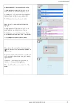
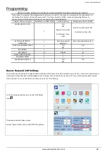
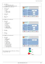
Indication of Day/Night Mode 

The panel indicates its current operating mode by means of a circle in the top left corner of the LCD. 

No Day / Night

 timer set. 

 
No circle in top left corner. 


Day / Night timer set. Panel in 

Day Mode

 
White circle in top left corner. 


Day / Night timer set. Panel in 

Night Mode

 
Black bar in top left corner. 


Summary of Contents for MMP

Page 1: ...Doc GLT 261 7 2 Issue 001 Date 09th September 2018 CONTROL PANEL Operation and Maintenance Manual...

Page 2: ...es Zone Labels Setting SLC Device Options Setting NCA NCB Module Options Setting ZMA ZMB MIM Module Options Setting MRM Module Options Event Logs Programming Cause and Effect Outputs and Delays Day Ni...

Page 3: ...once acknowledged Off when the supervisory condition is cleared some supervisory inputs may require a system reset if they are latched c LED Trouble Yellow LED Flashes when there s a fault with a mon...

Page 4: ...ent circuits devices in test mode j LED NAC Trouble Disablement Yellow LED On steady if there is a fault detected on an NAC circuit On steady when an NAC has been disabled Off when the NAC s are in th...

Page 5: ...er you press the SYSTEM RESET button all NACs control outputs and panel audio and visual indicators will reactivate The reset message is sent to the printer and the history log r Function Button Drill...

Page 6: ...ated below In the quiescent condition the panel displays System Healthy Velocity Logo The following functions will be performed when in the trouble condition Will cause the panel s internal buzzer to...

Page 7: ...latching or non Latching for each supervisory input The following functions will be performed when in the supervisory condition Will cause the panel s internal buzzer to sound with a pulsed output Th...

Page 8: ...n that zone are also disabled Press the zone icon SLC device icon or local I O for details of the disablements In this example there is a single SLC addressable device disabled Press the Device icon f...

Page 9: ...isplay the highest priority event It will display the presence of suppressed events as icons on the top right of the screen The number of events for each category is shown on the icon To display any o...

Page 10: ...bottom left corner of the LCD screen Full user access Access level 2b From access level 2a press the menu access icon This allows the user to view the user menus to view device status event logs etc...

Page 11: ...minutes Navigating the Panel Menus The Velocity panel has 2 menus user and engineer Entering the user code Default 0001 accesses the user menu Entering the Engineer password Default 9999 enables acce...

Page 12: ...presented in data fields the data will either be values or option buttons Clicking on the field will allow it to be edited Text Keyboard Used to enter text Use and to position the keyboard Press the...

Page 13: ...or Trouble Red for Alarm and Blue for supervisory The event that is next in the queue to be acknowledged will be blinking Press the ACK button to acknowledge the blinking event When an event has been...

Page 14: ...password Select Engineer and enter the Engineer Access Level 3 password default is 9999 Press the access menu icon followed by the system icon Select the Clock tab Edit the time and date as required P...

Page 15: ...ssword twice To delete a user enter the password as blank Any unused user should have the password left blank Press the exit button to leave the menu Press the green tick to confirm the changes Config...

Page 16: ...ng The Velocity fire system allows any number of devices to be allocated to a zone However it is assumed that a zone will not contain more than 32 fire detectors and or manual call points since this w...

Page 17: ...location of a fire that has been detected The address number of each point or device on the loop has already been set with the address programming tool VDOT AD2 See Manual GLT 303 7 1 for details The...

Page 18: ...he current mode of each device i e ENABLED or DISABLED Press the MODE field of a device to toggle its state between enabled and disabled The analogue values can be displayed by pressing the Real Time...

Page 19: ...device tap the device so that it s highlighted yellow then press the delete icon To manually add a device press the add icon Select the address and device type of the item being added Enter the point...

Page 20: ...Off Night settings Opt On Opt Off Heat On Heat Off VDOT DOP AC240 SCI Addressable Relay Dual Output Module For AC240V with SCI Available options Led Flash Off On VDOT DOP SCI Addressable Relay Dual Ou...

Page 21: ...sB NO SC ClassA NO SC P Priority Off On Note Turning on priority polling will make the panel prioritise events from this device This can only be used on 50 devices per loop VDOT SB Addressable Sounder...

Page 22: ...O SC Input Event Alarm Supervisory Trouble P Priority Off On Note Turning on priority polling will make the panel prioritise events from this device This can only be used on 50 devices per loop VDOT M...

Page 23: ...will be labelled on the TRM PCB inside the panel and are also shown in the Velocity Installation manual Doc GLT 261 7 1 The module settings screen will be displayed In this example the output address...

Page 24: ...D will be flashing When you have finished configuring the module output you can press the or arrows to change to the next output number on the module or press to exit and either confirm or dismiss the...

Page 25: ...the green tick to confirm Each input can be assigned to a zone To change the zone press either the or button to increase or decrease the zone number You can also type in the number via the panel numer...

Page 26: ...utput on the module itself E g a MRM that is plugged into TRM port 1 would have the following addresses 1 1 TRM Port 1 Output 1 1 2 TRM Port 1 Output 2 1 3 TRM Port 1 Output 3 To change the text label...

Page 27: ...ergised Supervisory Relay will act as a common supervisory relay and will react to ANY supervisory condition on the panel Cannot be disabled or controlled by cause effects To change the output type pr...

Page 28: ...a MAGENTA highlight The highlighted section gives the time date and the operation information The table shows more detail of the operation event The left hand column shows the event number Alarm even...

Page 29: ...gives the time date and the device type that has entered alarm verification The table shows more detail of the alarm verification event Address Device text label zone zone text label The left hand co...

Page 30: ...0s Confirmation Time 1 60s Retard Time Maximum 30s Confirmation Time 60s MULTIPLE DETECTOR OPERATION Y Set on two optical detectors Set on two optical detectors POSITIVE ALARM SEQUENCE Y ON OFF ON PRE...

Page 31: ...he panel The flashers of a notification appliance can be configured to remain flashing after the chimes horns have been silenced The flashers can only be stopped by pressing the panel reset button to...

Page 32: ...be programmed to generate output s e g operate one or more NAC or relay outputs in one or more zones The inputs and outputs can be selected from 4 categories Point Local I O Zone Panel Example of Sel...

Page 33: ...Zone cause the options are Zone causes Alarm Detector Alarm MCP Alarm Trouble Maintenance Supervisory ON Supervisory OFF Mlt devices in alarm Zone start 1 254 Zone end 1 254 For a Panel cause the opt...

Page 34: ...This defines whether the sounders will resound from a new alarm if they had been previously silenced The options are Never resound Resound on an alarm from a New zone Always resound for any new alarm...

Page 35: ...not set A Group Effects Evacuation on sounders Warning on sounders Activate Beacon Switch OFF SND Beacon Switch ON Relays Switch OFF Relays Evacuation on outputs Warning on outputs Switch OFF output D...

Page 36: ...sible to edit a cause effect line If a line needs to be altered it must be deleted tap the cause effect so that it becomes highlighted yellow and then press the delete icon The new statement can now b...

Page 37: ...ory Mains Fault Relay Output Delay In the event of a mains power failure the Velocity can be programmed to delay its TRM trouble relay for a time of between 0 240 minutes This is normally used when op...

Page 38: ...lay field If the delay is only to be set at certain times of the day the panel should be configured for day night mode See the following DAY NIGHT section for more details Switching Off Delays at Acce...

Page 39: ...one Day time period each day For example if a site closes for a 2 hour break the panel could be configured with 2 day time periods eg 8 00 12 00 and 14 00 18 00 Because of this the panel refers to ea...

Page 40: ...more than 4 slices programmed the panel displays up down scroll arrows in order to view the other slices To edit a slice tap that slice so that it is highlighted yellow and then press the delete icon...

Page 41: ...r the day time delay in the first delay field The delay is entered in seconds The maximum delay is 600 seconds 10 minutes If no night time delay is needed set the night time delay to Zero in the secon...

Page 42: ...ay time night time For the VDOT PYH Addressable Multisensory Detector there are settings for the smoke sensor and for the heat sensor The smoke sensor can be set to Off Low Normal or High Note setting...

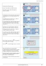
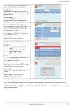
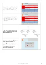
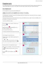
Page 43: ...panel indicates its current operating mode by means of a circle in the top left corner of the LCD No Day Night timer set No circle in top left corner Day Night timer set Panel in Day Mode White circle...

Page 44: ...will immediately activate all appropriate outputs and indicate the alarm condition If no additional detector alarms occur within 90 seconds of the first alarm 30 second Retard plus 60 second Confirmat...

Page 45: ...red between 1 60 seconds To change the time press either the or button to increase or decrease the zone number You can also type in the number via the panel numerical keyboard to do this press on the...

Page 46: ...condition Multiple Detector Operation Setup Multiple detector operation can be set up as follows Go to the engineer menu and select the Cause Effect icon The cause and effect table screen will be sho...

Page 47: ...ct Panel Evacuation on Sounders as the effect Press the to confirm the selections The panel shows the Programmed cause and effect It shows First row Event type Direct AND OR and entry number The progr...

Page 48: ...If a second alarm occurs during either time delays or if a manual alarm is activated this will immediately cause the activation of the appropriate outputs Positive Alarm Sequence Setup Positive alarm...

Page 49: ...The alarm will need to be acknowledged in order to start the secondary delay timer An acknowledged alarm event will change from flashing red to a solid white colour If the alarm is not acknowledged or...

Page 50: ...e achieved on a Velocity MMP system Ensure that when pre alarm operation is used that it complies with UL864 10th Edition requirements Go to the engineer menu and select the Cause Effect icon The caus...

Page 51: ...switch connected to a VDOT DIP SCI Addressable Dual Input Module with SCI at address Loop 1 Point 2 to allow manual activation of the general alarm evacuation signal This flow chart is a breakdown of...

Page 52: ...nning but doesn t want spurious false alarms The panel will respond in the usual manner to any events in any non disabled zones Any number of zones can be disabled but it is good practice to only disa...

Page 53: ...uts disabled The General Disablement LED will be lit and also the zonal disablement LEDs will be lit for any zone that is fully disabled The zonal disablement LEDs only apply to panels that have a ZLX...

Page 54: ...he Point menu Press on the Mode field for the device to be disabled Select further devices to disable if necessary and then press Exit to save When SLC devices have been disabled the LCD display chang...

Page 55: ...arm Group Explorer Global Mode Disablement When Global mode is set to disabled the panel will not activate any alarm group devices This might be used if the system requires routine maintenance and the...

Page 56: ...hanges Press tick to save the changes or press to discard Change the global mode for sounder status to disable by pressing the Disabled selection area The text will change from All enabled to All disa...

Page 57: ...nts in any non disabled zones Any number of alarm group zones can be disabled but it is good practice to only disable one alarm group zone at a time An alarm group zone can be disabled as follows Ente...

Page 58: ...es icon or the disabled local I O icon If any zones have all of their outputs disabled it will be indicated by the disabled zone outputs icon To re enable a zone use the same procedure pressing the Ou...

Page 59: ...port 3 would have the following addresses 3 1 TRM Port 3 Input 1 3 2 TRM Port 3 Input 2 3 3 TRM Port 3 Input 3 To disable an input change the mode by pressing on the Disabled selection circle then pre...

Page 60: ...Output 1 2 2 TRM Port 2 Output 2 To disable an input change the mode by pressing on the Disabled selection circle then press or to cycle through more inputs or the exit icon The panel will ask if you...

Page 61: ...bove the alarm threshold the device will be triggered again and the Alarm sounders will operate again Should an Alarm occur on a zone that is not programmed to test the Fire Alarm Panel will operate a...

Page 62: ...e test alarms are reported on the supervisory screen When the testing is complete take the panel out of test mode by entering the Engineer level menu and selecting the zone icon Select the zone s to b...

Page 63: ...tter fault tolerance Network Typologies Ring Network Class A In a ring network each control panel is connected to 2 other control panels to form a ring This has the same topology as the loops of addre...

Page 64: ...be labelled on the TRM PCB inside the panel and are also shown in the Velocity Installation manual Doc GLT 261 7 1 The panel shows that the network connection is disabled It s default state Press the...

Page 65: ...e addresses seen and whether the panel sees a connection on Network port A NET 1 and Network port B NET 2 If the panel sees a connection it reports the port as UP If it does not see a connection it re...

Page 66: ...panel shows that the TCP IP connection is disabled It s default state Select DHCP for the LAN to assign the settings or select manual to enter the settings by hand If entering the settings by hand ju...

Page 67: ...menu press the Cloud tab Enter Server and Port details as required Make a note of the MAC address as this will be needed to register the panel at the server Note That the server can be entered as a U...

Page 68: ...tick to confirm the selection The port number will be labelled on the TRM PCB inside the panel and are also shown in the Velocity Installation manual Doc GLT 261 7 1 The panel shows the RS232 printer...

Page 69: ...with maintenance personnel to ensure that cleaning maintenance or building work does not interfere with the functioning and reliability of the fire alarm system 9 Ensure any changes to the system are...

Page 70: ...rsonnel only Carry out a complete wiring check in accordance with the testing and inspection requirements of the relevant National wiring regulations in the UK this is the IEE Wiring Regulations The B...

Page 71: ...the search is complete In this example the break is between address 154 which is seen from side A only and address 155 which is seen from side B only This only applies if the loop is addressed sequent...

Page 72: ...o external wiring has been connected to the loop Split the loop and check each half at a time trying to find the over current fault Continue splitting the side reporting a problem until the source is...

Page 73: ...Mini IP and Sounder base Try removing the known device for that address and perform a loop learn The detail screen should indicate what type of device is now seen at that address which should help re...

Page 74: ...K An Output interface has detected that its output relay has stuck Reset the panel and test again If the fault returns the interface will need to be replaced ISOLATOR FAULT The internal short circuit...

Page 75: ...ce if necessary Batteries normally have to be replaced every 4 5 years Charger Fault The panel has determined that the power supply is not charging the batteries Try power cycling the panel If the fau...

Page 76: ...s occur on the field wiring As a first check disconnect field wiring from the Velocity Panel If no earth fault is reported then fault is on the field wiring Locate the fault by reconnecting one field...

Page 77: ...ne resistor is the correct value if required Local Output Open The output on one of the module ports has detected an open circuit Check that the wiring connections are making good contact Check that t...

Page 78: ...rk module has lost communications with the panel connected to it s NET 2 Port Check for cable breaks Check for cable shorts Check the heartbeat LED on the network module in both panels NODE IS UNREACH...

Page 79: ...View Event Log Local I O Zone Class A View input 1 3 text label View input 1 3 zone allocation View input 1 3 type Alarm Supervisory View Edit input 1 3 status Disabled Enabled Zone Class B View input...

Page 80: ...n View output 1 2 type Sounder Bell Voltage View Edit output 1 2 mode Disabled Enabled LCD LED Test panel LEDs LCD Buzzer Delays Toggle panel delays on or off Alarm Group Global Mode View Edit Relay S...

Page 81: ...t Sounder Point Basic View Address Device type View Edit Device text label View Edit Device mode Enabled disabled View Edit Device Zone allocation Real Time View Address Device type View Device text l...

Page 82: ...Disabled Enabled Day Night Configure day night timer add day settings LCD LED Test panel LEDs LCD Buzzer Network RS485 Network View Edit RS485 Port status Disabled Enabled local Enabled Global View Ed...

Page 83: ...ON Supervisory OFF Mlt devices in alarm Panel Alarm Detector Alarm MCP Alarm Trouble Maintenance Supervisory ON Supervisory OFF Mlt devices in alarm Mlt Zones in alarm Panel KeySwitch ON Panel KeySwit...

Page 84: ...Output Panel 0 600 0 600 Evacuation on sounders Warning on sounders Activate Beacon Switch off SND Beacon Switch ON Relays Switch OFF Relays Evacuation on Outputs Warning on Outputs Switch off Output...

Reviews: