69
107774-02- 4/18
VIII. Gas Piping
(continued)
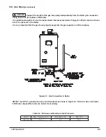
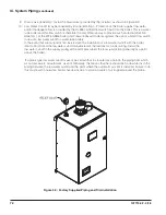
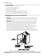
Figure 8.1: Gas Connection to Boiler
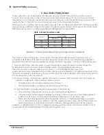
Model
Max. (Natural & LP)
Min. (Natural)
Min. (LP)
135-180
14.0”
2.5”
11.0”
Table 8.2: Minimum and Maximum Inlet Pressures
NOTICE
Install 1/2” ground joint union (nut side down) as shown in Figure 8.1. Failure to do so will make
it difficult or impossible to remove burner for servicing.
CAUTION Support the weight of the gas line piping independently from the boiler gas connection
fitting located on the bottom of the boiler.
If an additional regulator is used to reduce boiler inlet pressure below 1/2 psig (3.4 kPa) it must be at least
6 to 10 ft. upstream of the boiler.
It is very important that the gas line is properly purged by the gas supplier or utility company.
Summary of Contents for K2WTC-135
Page 81: ...81 107774 02 4 18 X Domestic Hot Water Piping continued Figure 10 1 Domestic Hot Water Piping...
Page 89: ...89 107774 02 4 18 XI Wiring continued...
Page 90: ...90 107774 02 4 18 Figure 11 8 Internal Wiring Connections Diagram XI Wiring continued...
Page 101: ...101 107774 02 4 18 Lighting and Operating Instructions XII Start Up and Checkout continued...
Page 142: ...142 107774 02 4 18 XVI Repair Parts continued...
Page 145: ...145 107774 02 4 18 XVI Repair Parts continued...
Page 148: ...148 107774 02 4 18 XVI Repair Parts continued...
Page 150: ...150 107774 02 4 18 XVI Repair Parts continued...
Page 152: ...152 107774 02 4 18 XVI Repair Parts continued 120 121 122 123 124 125 126 127...
Page 159: ...159 107774 02 4 18 SERVICE RECORD DATE SERVICE PERFORMED...

