


71
107774-02- 4/18
IX. System Piping
(continued)
B. Standard Piping Installation Requirements
Observe the following requirements when installing the boiler piping:
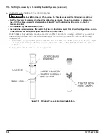
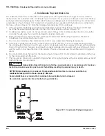
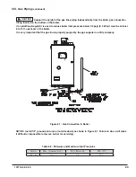
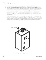
1. Relief Valve (Required) – The relief valve is shipped loose and must be installed in the location shown
in Figure 9.0. Pipe the outlet of the relief valve to a location where water or stream will not
create a hazard or cause property damage if the valve opens. The end of the discharge pipe must
terminate in unthreaded pipe. If the relief valve discharge is not piped to a drain, it must terminate
at least 6” above the floor. Do not run the discharge piping through an area that is prone to freezing.
The termination of the relief valve must be in an area where it is not likely to become plugged by debris.
The relief valve supplied with the boiler is set to open at 30 psi. If it is replaced, the replacement
must have a setting less than or equal to the maximum allowable working pressure (MAWP) shown on
the ASME data plate located on the left side of the heat exchanger.
2. Circulator (required) – The boiler loop circulator is factory installed inside the boiler cabinet. Usually at
least one addition circulator (not supplied) will be required for the system to work properly. See the
following section for more information.
3. Expansion Tank (required) – If this boiler is replacing an existing boiler with no other changes in the
system, the old expansion tank can generally be reused. If the expansion tank must be replaced,
consult the expansion tank manufacturer’s literature for proper sizing. If using antifreeze, account for
additional expansion of glycol solution when sizing an expansion tank. In a typical residential heating
system, a glycol mixture has an expansion rate about 1.2 times that of water alone, therefore a tank for
an anti-freeze system should be at least 1.2 times greater in size.
4. Fill Valve (required) – Either a manual or automatic fill valve may be used, but a manual valve is preferred
because it eliminates unmonitored additions of make-up water to the system. The ideal location for the
fill valve is at the expansion tank. If using antifreeze with automatic fill valve, it is recommended to install
a water meter to monitor makeup water. Antifreeze concentration will decrease as makeup water is
added. If using antifreeze, local codes often require a backflow preventer or disconnect from city water.
5. Automatic Air Vent (required) – At least one automatic air vent is required. Manual air vents will usually
be required in other parts of the system to remove air during initial fill.
6. Manual Reset High Limit (required by some codes) - This control is required by ASME CSD-1 and some
other codes. Install the high limit in the boiler supply piping just above the boiler with no intervening
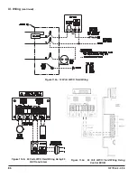
valves. Set the manual reset high limit to 200°F. Wire the limit per Figure 11.3 in the Wiring section.
7. Isolation Valves (recommended) - Isolation valves are useful when the boiler must be drained, as they
will eliminate having to drain and refill the entire system.
8. Strainer (recommended) – Install a Y Strainer, or other suitable strainer, to prevent any system debris
from entering the boiler and fouling the water passages. Note that some strainers have a significant
pressure drop, which may impact the ability of the boiler pump to obtain the required flow. See Part C of
this section for additional information.
DANGER
Explosion / Scald Hazard. Pipe relief valve discharge to a location where the potential
of severe burns is eliminated.
Do not install a relief valve having a setting greater than the MAWP shown on the rating plate.
Do not install a valve in the relief valve discharge line.
Do not install relief valve in a location other than that specified by the factory.
Do not plug the relief valve discharge.
•
•
•
•
Summary of Contents for K2WTC-135
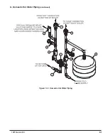
Page 81: ...81 107774 02 4 18 X Domestic Hot Water Piping continued Figure 10 1 Domestic Hot Water Piping...
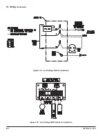
Page 89: ...89 107774 02 4 18 XI Wiring continued...
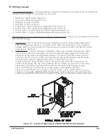
Page 90: ...90 107774 02 4 18 Figure 11 8 Internal Wiring Connections Diagram XI Wiring continued...
Page 101: ...101 107774 02 4 18 Lighting and Operating Instructions XII Start Up and Checkout continued...
Page 142: ...142 107774 02 4 18 XVI Repair Parts continued...
Page 145: ...145 107774 02 4 18 XVI Repair Parts continued...
Page 148: ...148 107774 02 4 18 XVI Repair Parts continued...
Page 150: ...150 107774 02 4 18 XVI Repair Parts continued...
Page 152: ...152 107774 02 4 18 XVI Repair Parts continued 120 121 122 123 124 125 126 127...
Page 159: ...159 107774 02 4 18 SERVICE RECORD DATE SERVICE PERFORMED...


