


45
107774-02- 4/18
VII. Venting
E. Assembly of CPVC/PVC Vent Systems (continued)
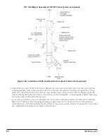
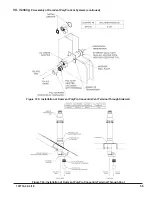
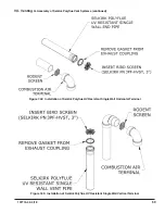
Figure 7.27: Vent Connections and Flue Gas Sample Cap Location
c. There is a 0” minimum clearance between the air intake piping and all types of construction.
d. To the extent possible, pitch horizontal air intake piping towards the outdoors.
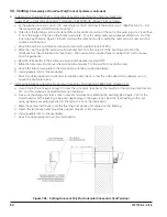
3. Installation of Horizontal Fitting Terminals (Terminal Option A):
a. See Figure 7.28 for proper orientation of twin pipe horizontal terminals. Outer edge of both terminals must be
within 10” from wall surface. (Figure 7.6)
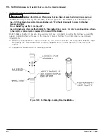
b. If desired, the terminals can be attached to the end of the vent and/or intake pipes with field supplied
stainless steel screws so that they can be later removed for cleaning and inspection. If this is done, drill a
clearance hole in the coupling or
elbow and a tap hole in the end of the vent/intake pipes to accept these screws.
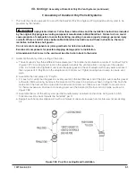
c. If these terminals are installed on snorkels, assemble the snorkels as shown in Figure 7.12. Brace the vertical
run of piping on the building exterior as required.
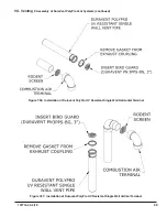
4. Installation of Vertical Fitting Terminals (Terminal Option H):
a. See Figure 7.29
for the proper orientation of twin pipe vertical terminals.
b. The coupling is used to secure the rodent screen to the end of the vent pipe.
c. A 180° bend (or two 90° elbows) are installed on the top of the air intake pipe. If two 90° elbows are used, a
rodent screen can be installed between them (Figure 7.29). If a 180° bend is used, install a rodent screen in
the open side of the bend, using a ring made of PVC pipe. If desired, the termination fittings can be attached
to the end of the vent and/or intake pipes with field supplied stainless steel screws so that they can be later
removed for cleaning and inspection. If this is done, drill a clearance hole in these fittings and a tap hole in
the end of the vent/intake pipes to accept these screws.
d. Use roof flashings and storm collars to prevent moisture from entering the building. Seal the roof flashing to
the roof using generally accepted practice for the type of roof on the installation. Apply RTV to seal the storm
collars to the vent and intake pipes.
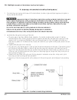
5. Installation of IPEX low profile vent terminal (Terminal Option B) - See Figure 7.30:
a. Cut two holes in wall to accommodate the size PVC pipe being used. The distance between hole centers is
5.6”.
b. Slide both vent and intake air pipes through the holes, and cement them to the base of the vent termination kit
using a primer and cement listed for use with PVC.
Summary of Contents for K2WTC-135
Page 81: ...81 107774 02 4 18 X Domestic Hot Water Piping continued Figure 10 1 Domestic Hot Water Piping...
Page 89: ...89 107774 02 4 18 XI Wiring continued...
Page 90: ...90 107774 02 4 18 Figure 11 8 Internal Wiring Connections Diagram XI Wiring continued...
Page 101: ...101 107774 02 4 18 Lighting and Operating Instructions XII Start Up and Checkout continued...
Page 142: ...142 107774 02 4 18 XVI Repair Parts continued...
Page 145: ...145 107774 02 4 18 XVI Repair Parts continued...
Page 148: ...148 107774 02 4 18 XVI Repair Parts continued...
Page 150: ...150 107774 02 4 18 XVI Repair Parts continued...
Page 152: ...152 107774 02 4 18 XVI Repair Parts continued 120 121 122 123 124 125 126 127...
Page 159: ...159 107774 02 4 18 SERVICE RECORD DATE SERVICE PERFORMED...


