


77
107774-02- 4/18
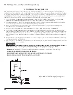
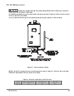
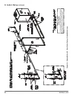
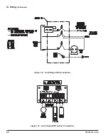
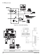
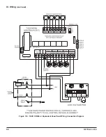
Figure 9.6: Piping Method #2 - Direct Connection of Boiler to Heating System
Method 2: Direct Connection to Heating System (Generally NOT Recommended)
In some relatively rare cases it may be possible to connect this boiler directly to the heating system as is done
with conventional boilers (Figure 9.6). If this is done, the flow rate through the boiler will equal the flow rate
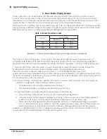
through the system. The flow rate through the system must therefore always remain within the limits shown in
Table 9.1. For this reason, the pressure drop through the entire system must be known.
This method is generally not recommended because it is often very difficult to accurately calculate the pressure
drop through the system. In replacement installations, it may be impossible to get an accurate measurement of
the amount of piping and number of fittings in the system. In addition, if the system is zoned, the system flow
may drop well below the minimum required when only one zone is calling for heat.
The one advantage to this method is its installation simplicity. It may make sense to use this method when the
boiler is to be installed with a new single zone system having a low-pressure drop.
Figure 9.7 shows the performance curve for the pump in each boiler model, taking into account the pressure
drop through the boiler’s heat exchanger and internal piping. These curves therefore show the flow that can be
achieved through the boiler as a function of the pressure drop through the connected piping. Calculation of the
system pressure drop must be performed by someone having familiarity with pressure drop calculations, such
as an HVAC engineer.
IX. System Piping
(continued)
NOTICE
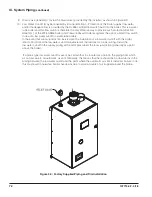
Where it is not possible to install a separate boiler loop, the system circulator must be sized to
ensure that the flow through the boiler stays within the defined parameters to prevent overheating when
the boiler is fired at it’s full rated input. Install a flow meter to measure the flow, or fire the boiler at full
rate and ensure the boiler delta T does not exceed 35°F (19°C).
Summary of Contents for K2WTC-135
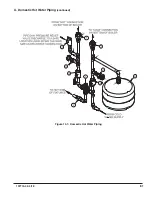
Page 81: ...81 107774 02 4 18 X Domestic Hot Water Piping continued Figure 10 1 Domestic Hot Water Piping...
Page 89: ...89 107774 02 4 18 XI Wiring continued...
Page 90: ...90 107774 02 4 18 Figure 11 8 Internal Wiring Connections Diagram XI Wiring continued...
Page 101: ...101 107774 02 4 18 Lighting and Operating Instructions XII Start Up and Checkout continued...
Page 142: ...142 107774 02 4 18 XVI Repair Parts continued...
Page 145: ...145 107774 02 4 18 XVI Repair Parts continued...
Page 148: ...148 107774 02 4 18 XVI Repair Parts continued...
Page 150: ...150 107774 02 4 18 XVI Repair Parts continued...
Page 152: ...152 107774 02 4 18 XVI Repair Parts continued 120 121 122 123 124 125 126 127...
Page 159: ...159 107774 02 4 18 SERVICE RECORD DATE SERVICE PERFORMED...


