


70
107774-02 - 4/18
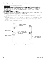
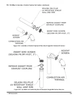
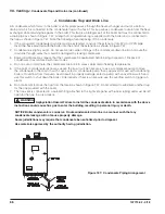
IX. System Piping
A. General System Piping Precautions
WATER QUALITY AND BOILER WATER ADDITIVES
IMPORTANT NOTE
The heat exchanger used in this boiler is made from stainless steel coils having relatively narrow waterways.
Once filled with system water, it will be subjected to the effects of corrosion, as well as fouling from any debris
introduced from the system. Take the following precautions to minimize the chance of severe heat exchanger
damage caused by corrosion and/or overheating:
1 Flush the system before connecting the boiler - In a replacement installation, flushing the system will remove
impurities, such as sediment, solder flux, metal shavings, and traces of old boiler additives. Even if the
system is new, do not omit this step – new systems will contain flux and may even contain some of the other
impurities listed above. Flush the system completely and repeat if necessary to completely remove these
contaminants. If necessary, a cleaning agent may be used to assist in system cleaning. See Section XII
(“Start-up and Check-out”) for recommended cleaners.
2. Make sure that the system is tight - This is the single most important guideline. Tap water contains dissolved
oxygen which causes corrosion. In a tight system, this oxygen comes out of solution and is quickly removed
from the system through the automatic air vent. The system then remains essentially free of oxygen. If the
system is not tight, however, frequent additions of make-up water can expose the heat exchanger to oxygen
on a continuous basis. In addition, frequent additions of hard make-up water can cause calcium deposits to
collect in the heat exchanger, causing severe damage. To minimize additions of make-up water:
• Inspect the system thoroughly for leaks before placing it in service.
• If the system includes underground piping, or other piping in which a leak might go undetected,
consider isolating the boiler from the system with a heat exchanger.
• Make sure that the expansion tank is properly sized and in good condition. If it is not, the relief valve
may open frequently, resulting in regular additions of make-up water.
• If an automatic fill valve is installed, installation of a water meter in the fill line is strongly recommended
so that routine additions of make-up water can be detected and their cause corrected.
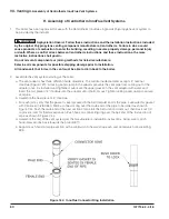
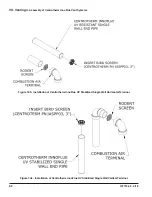
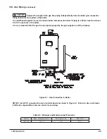
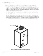
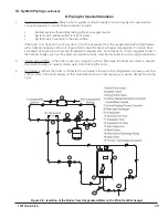
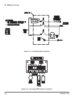
3. Non-Metallic Tubing - Even if the system is tight, oxygen can be introduced into the system through some
types of non-metallic tubing used in radiant or snow melt systems. Other nonmetallic tubing is equipped
with an oxygen barrier to prevent migration of oxygen into the water. If the boiler is to be installed in a
system containing non-metallic tubing without an oxygen barrier, it must be isolated from the boiler with a
heat exchanger as shown in Figure 9.8.
4. Water Chemistry, Antifreeze, and Boiler Water Additives – Improper boiler water chemistry can cause the
heat exchanger damage described above, as well as deterioration of seals. Observe the water chemistry
requirements shown in Section XII (“Start-up and Check-out”).
CAUTION
1. The heat transfer-medium must be water or other nontoxic fluid having a toxicity rating or Class of 1,
as listed in Clinical Toxicology of Commercial Products, 5th edition.
2. The pressure of the heat transfer medium must be limited to a maximum of 30 PSIG by an approved
safety or relief valve.
WARNING Failure to properly pipe boiler may result in improper operation and damage to boiler or
structure.
Install boiler so that the gas ignition system components are protected from water (dripping, spraying,
rain, etc.) during boiler operation and service (circulator replacement, etc.).
Oxygen contamination of boiler water will cause corrosion of iron and steel boiler components and can
lead to boiler failure. Warranty does not cover problems caused by oxygen contamination of boiler water
or scale (lime) build-up caused by frequent addition of water.
•
•
Summary of Contents for K2WTC-135
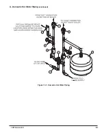
Page 81: ...81 107774 02 4 18 X Domestic Hot Water Piping continued Figure 10 1 Domestic Hot Water Piping...
Page 89: ...89 107774 02 4 18 XI Wiring continued...
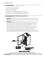
Page 90: ...90 107774 02 4 18 Figure 11 8 Internal Wiring Connections Diagram XI Wiring continued...
Page 101: ...101 107774 02 4 18 Lighting and Operating Instructions XII Start Up and Checkout continued...
Page 142: ...142 107774 02 4 18 XVI Repair Parts continued...
Page 145: ...145 107774 02 4 18 XVI Repair Parts continued...
Page 148: ...148 107774 02 4 18 XVI Repair Parts continued...
Page 150: ...150 107774 02 4 18 XVI Repair Parts continued...
Page 152: ...152 107774 02 4 18 XVI Repair Parts continued 120 121 122 123 124 125 126 127...
Page 159: ...159 107774 02 4 18 SERVICE RECORD DATE SERVICE PERFORMED...


