


63
107774-02- 4/18
VII. Venting
H. Assembly of Centrotherm InnoFlue Vent Systems
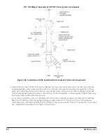
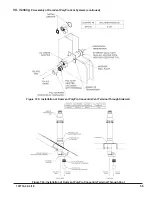
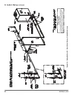
6. Installations using InnoFlue Flex (Vent Options 10 & 17):
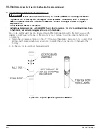
Refer to Centrotherm InnoFlue Instructions for assembly of all flex components including the chimney cap and
the adaptor to rigid InnoFlue at the base of the masonry or B vent chimney. In addition, observe the following
requirements:
a. Refer to the appropriate Vent option in Tables 7.13b or 7.21 for a list of the principle flex components required.
Rigid vent pipe by the same manufacturer will also be required for the run from the boiler to the base of
chimney.
b. Masonry chimneys cannot be used for an air chase
c. B vent chimneys can only be used for an air chase (Vent option 10) if the B vent has the minimum size shown
in Table 7.13b and is fully accessible for sealing of all joints and seams.
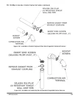
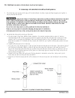
d. When Vent Option 10 is used, install a Tee of the same size at the base of the vent. Route the smooth section
of InnoFlue Flex (3”) through a cap in the base of this Tee. Use a Centrotherm IAWP03B wall plate and RTV to
seal this penetration. Install the Base Support using the Base support bracket as described in the InnoFlue
installation manual.
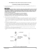
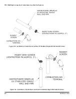
Connection of the PVC air intake pipe to the side outlet of the tee is made using a cap and a PVC socket x
male thread adaptor. Cut a clearance hole in the cap for the male threads. Secure the adaptor to the cap
using a 3” electrical conduit lock nut. Seal all joints with RTV.
WARNING Asphyxiation Hazard. When using InnoFlue Flex, observe the following precautions:
• InnoFlue Flex may be damaged by handling at low temperatures. Do not bend, uncoil or attempt to
install if it has been stored at a temperature below 42°F without allowing it to warm to a higher
temperature first.
• Do not bend InnoFlue Flex more than 45°.
• Instructions below reference the Centrotherm InnoFlue instruction manual. Not all vent configurations
shown in the Centrotherm manual are approved for use with this boiler.
Summary of Contents for K2WTC-135
Page 81: ...81 107774 02 4 18 X Domestic Hot Water Piping continued Figure 10 1 Domestic Hot Water Piping...
Page 89: ...89 107774 02 4 18 XI Wiring continued...
Page 90: ...90 107774 02 4 18 Figure 11 8 Internal Wiring Connections Diagram XI Wiring continued...
Page 101: ...101 107774 02 4 18 Lighting and Operating Instructions XII Start Up and Checkout continued...
Page 142: ...142 107774 02 4 18 XVI Repair Parts continued...
Page 145: ...145 107774 02 4 18 XVI Repair Parts continued...
Page 148: ...148 107774 02 4 18 XVI Repair Parts continued...
Page 150: ...150 107774 02 4 18 XVI Repair Parts continued...
Page 152: ...152 107774 02 4 18 XVI Repair Parts continued 120 121 122 123 124 125 126 127...
Page 159: ...159 107774 02 4 18 SERVICE RECORD DATE SERVICE PERFORMED...


