AC300 Series Vector Control Inverter Manual
Function Parameter Specifications
72
2.
Terminal jog has the highest priority command right. That is, in any state, once the terminal jog
command is valid, the jog acceleration/deceleration time is immediately run from the current running
frequency to the jog frequency.
3.
Only the terminal jog run priority is not limited by the run command channel, and other jog commands
have priority only when they are the same as the run command channel. For example, the keyboard jog
operation is valid only when the keyboard control is running, and takes precedence over the keyboard
forward/reverse run command.
4.
The set value of the jog running frequency is limited by the maximum frequency of [F00.09].
The actual output frequency during jog operation is limited by the upper limit frequency of [F00.11].
F01.41
Jump frequency 1
Setting range: 0.00
~
Maximum frequency
Default:
0.00Hz
F01.42
Jump frequency range 1
Setting range: 0.00
~
Maximum frequency
Default:
0.00Hz
F01.43
Jump frequency 2
Setting range: 0.00
~
Maximum frequency
Default:
0.00Hz
F01.44
Jump frequency range 2
Setting range: 0.00
~
Maximum frequency
Default:
0.00Hz
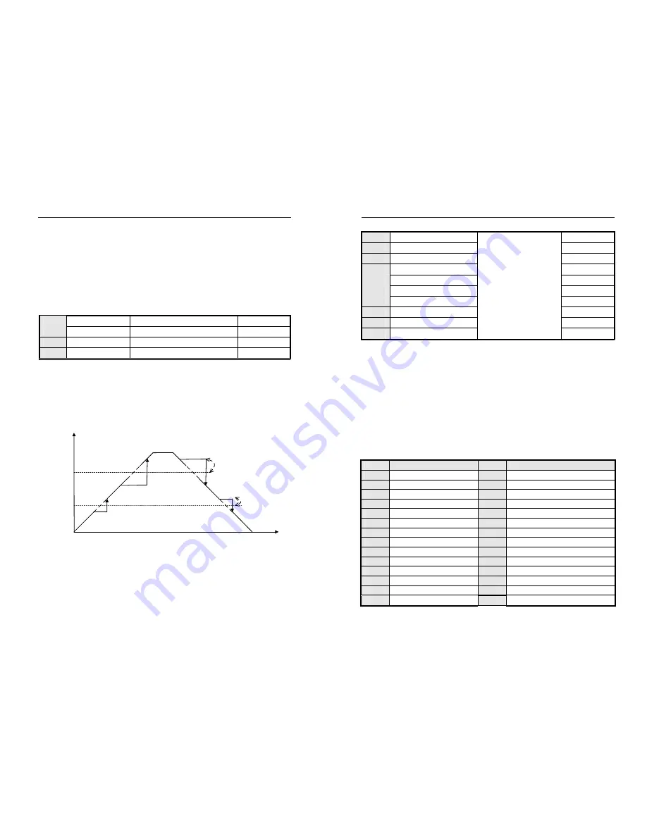
When the inverter is running with load, in order to avoid the output frequency of the inverter from the resonance
frequency point of the mechanical load, the resonance frequency can be avoided by the jump frequency. The inverter
can set two jumping points to perform the jump. After setting the skip frequency parameter, even if the set frequency of
the inverter is within the resonant frequency point of the mechanical load, the output frequency of the inverter will be
automatically adjusted to the outside of the resonant frequency of the mechanical load to avoid running at the
resonance point, the skip frequency processing during acceleration and deceleration is as follows:
Output
frequency
t
0
Jump
frequency
1
Jump
frequency
2
Output frequency
amplitude 2
Jump frequency
amplitude 1
Jump frequency and range diagram
Tips: During acceleration and deceleration, the output frequency of the inverter will still pass through the jump
frequency zone normally.
8.3
Switching Value Terminal Parameters
AC300 Series Vector Control Inverter Manual
Function Parameter Specifications
73
F02.00 Input
terminal
1(X1)
Setting range: 0
~
63
Default: 1
F02.01
Input terminal 2(X2)
Default: 2
F02.02
Input terminal 3(X3)
Default: 4
F02.03
Input terminal 4(X4)
Default: 5
F02.04
Input terminal 5(X5)
Default: 39
F02.05
Input terminal 6(X6 expand)
Default: 0
F02.06
Input terminal 7(X7 expand)
Default: 0
F02.07
Input terminal 8(X8 expand)
Default: 0
F02.08
Input terminal 9(X9 expand)
Default: 0
F02.09 Input
terminal
10(X10 expand)
Default: 0
This unit has 5 multi-function input terminals.
The functions of the multi-function input terminals (X1-X10) can be defined separately by the parameters
[F02.00~F02.09].
Set the characteristics of the multi-function input terminal and the detection delay by parameter [F02.11~F02.22]. For
details, see parameter [F02.11~F02.22].
Set the terminal characteristics of the multi-function input terminal [X5/PUL] with parameter [F02.04]. When set to "39:
Frequency selection", the external terminal is a high-speed pulse port, which is used as a PUL reference function;
otherwise, the external terminal is a digital signal input port, which is used as an X5 input. ([F02.09] Multi-function
terminal X10/PUL settings are the same)
The multi-function input terminals are versatile and can be easily set and selected as needed. The set values and
functions are as follows:
X
Function Specification
X
Function Specification
0 No
function
32
ACC/DEC time selection terminal 1
1 FWD
33
ACC/DEC time selection terminal 2
2 REV
34 ACC/DEC
pause
3 3-line
running(Xi)
35
Swing frequency input
4 FWD
JOG
36
Swing frequency pause
5 REV
JOG
37
Swing frequency reset
6 Free
stop
38
Keyboard self-test
7 Emergency
stop
39
Frequency selection
8 Malfunction
reset
40
Timer trigger terminal
9
External malfunction input
41 Timer
clear
terminal
10 Frequency
UP
42 Counter
input
terminal
11 Frequency
DW
43 Counter
clear
terminal
12 UP/DW
clear
44
DC braking command
13
Switch channel A to channel B
45
Pre excitation command terminal


