background image

25

4 Mounting

VEGAPULS 67 • Profibus PA

36533-EN-170405

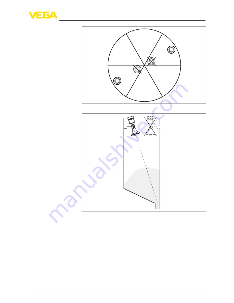
Fig. 20: Installation and orientation in multiple chamber silos

Fig. 21: Installation and orientation in multiple chamber silos

Air rinsing is useful for avoiding buildup, particularly when there is 

strong condensation. Since VEGAPULS 67 has no direct rinsing air 

connection, a separate rinsing air connection must be provided in 

the mounting socket. By inclining this connection towards the top, a 

particularly effective cleaning of the antenna cover is achieved.

Air rinsing

Summary of Contents for VEGAPULS 67

Page 1: ...Operating Instructions Radar sensor for continuous level measurement of bulk solids VEGAPULS 67 Profibus PA Document ID 36533 ...

Page 2: ...structions 14 4 2 Collar or adapter flange 15 4 3 Mounting strap 15 4 4 Mounting instructions 17 5 Connecting to the bus system 5 1 Preparing the connection 27 5 2 Connecting 28 5 3 Wiring plan single chamber housing 29 5 4 Wiring plan double chamber housing 30 5 5 Wiring plan double chamber housing Ex d ia 32 5 6 Double chamber housing with VEGADIS Adapter 33 5 7 Wiring plan version IP 66 IP 68 1...

Page 3: ...re update 70 9 7 How to proceed if a repair is necessary 70 10 Dismount 10 1 Dismounting steps 71 10 2 Disposal 71 11 Supplement 11 1 Technical data 72 11 2 Communication Profibus PA 79 11 3 Dimensions 83 11 4 Industrial property rights 91 11 5 Trademark 91 Safety instructions for Ex areas Take note of the Ex specific safety instructions for Ex applications These instructions are attached as docum...

Page 4: ...onnel and put into practice by them 1 3 Symbols used Information tip note This symbol indicates helpful additional information Caution If this warning is ignored faults or malfunctions can result Warning If this warning is ignored injury to persons and or serious damage to the instrument can result Danger If this warning is ignored serious injury to persons and or destruction of the instrument can...

Page 5: ...tions This is a state of the art instrument complying with all prevailing regulations and directives The instrument must only be operated in a technically flawless and reliable condition The operator is responsible for the trouble free operation of the instrument During the entire duration of use the user is obliged to determine the compliance of the necessary occupational safety measures with the...

Page 6: ...ard in field instrumentation The device fulfils the requirements of the following NAMUR recom mendations NE 21 Electromagnetic compatibility of equipment NE 53 Compatibility of field devices and display adjustment components NE 107 Self monitoring and diagnosis of field devices For further information see www namur de 2 7 Radio license for Europe The instrument was tested according to the latest i...

Page 7: ...ism that does not allow the main beam of the transmitter to be mounted vertically downward is prohibited This device shall be installed only at fixed locations The LPR device shall not operate while being moved or while inside a mov ing container Hand held applications are prohibited Marketing to residential consumers is prohibited Changes or modifications not expressly approved by the manufac tur...

Page 8: ...7 12 W For devices not meeting this 10 km separation e g those in the Okanagan Valley British Co lumbia the installer user must coordinate with and obtain the written concurrence of the Director of the DRAO before the equipment can be installed or operated The Director of the DRAO may be contacted at 250 497 2300 tel or 250 497 2355 fax Alternatively the Man ager Regulatory Standards Industry Cana...

Page 9: ... leur utilisateur La personne qui installe utilise ce capteur de niveau doit s assurer qu il se trouve à au moins 10 km de l Observatoire fédéral de radioas trophysique OFR de Penticton en Colombie Britannique Les coor données de l OFR sont latitude N 49 19 15 longitude O 119 37 12 La personne qui installe utilise un dispositif ne pouvant respecter cette distance de 10km p ex dans la vallée de l O...

Page 10: ...ass 14 ID numbers instrument documentation 15 Reminder to observe the instrument documentation The type label contains the serial number of the instrument With it you can find the following instrument data on our homepage Product code HTML Delivery date HTML Order specific instrument features HTML Operating instructions and quick setup guide at the time of ship ment PDF Order specific sensor data ...

Page 11: ...he instrument is also suitable for applications in liquids The antenna of the radar sensor emits short radar pulses with a duration of approx 1 ns These pulses are reflected by the product and received by the antenna as echoes The transit time of the radar pulses from emission to reception is proportional to the distance and hence to the level The determined level is converted into an appropri ate...

Page 12: ...justment devices 1 Smartphone tablet iOS or Android operating system PC notebook with Bluetooth USB adapter Windows operating system You can find further information in the operating instructions Display and adjustment module PLICSCOM Document ID 27835 The interface adapter VEGACONNECT enables the connection of communication capable instruments to the USB interface of a PC For parameter adjustment...

Page 13: ...information in the supplementary instructions Overvoltage arrester B81 35 Document ID 50708 Screwed flanges are available in different versions according to the following standards DIN 2501 EN 1092 1 BS 10 ASME B 16 5 JIS B 2210 1984 GOST 12821 80 You can find additional information in the supplementary instructions manual Flanges according to DIN EN ASME JIS The protective cover protects the sens...

Page 14: ... instrument exposed to the process are suitable for the existing process conditions These are mainly Active measuring component Process fitting Process seal Process conditions in particular are Process pressure Process temperature Chemical properties of the medium Abrasion and mechanical influences You can find detailed information on the process conditions in chapter Technical data as well as on ...

Page 15: ...he housing versions plastic aluminium single chamber and stainless steel the collar flange can be placed directly over the hous ing With the aluminium double chamber housing retroactive mount ing in this way is not possible the mounting type must be specified with the order You can find drawings of these mounting options in chapter Dimen sions Fig 2 Flange mounting of the radar sensor 4 3 Mounting...

Page 16: ...chnical data Required tools Allen wrench size 4 There are two ways to screw the strap onto the sensor Depending on the selected version the sensors can be swivelled in the strap as follows Single chamber housing Angle of inclination 180 infinitely variable Angle of inclination in three steps 0 90 and 180 Double chamber housing Angle of inclination 90 infinitely variable Angle of inclination in two...

Page 17: ...tated in the technical data The emitted radar impulses of the radar sensor are electromagnetic waves The polarisation is the direction of the electrical share With radar sensors the polarisation can be used to reduce the effect of false echoes considerably by turning the instrument in the connection flange or mounting boss The position of the polarisation is marked on the instrument 1 Fig 6 Positi...

Page 18: ...s the microwave signal will be interferred The optimum mounting position is on the opposite of the filling To avoid strong pollution the distance to the filter or dust extraction must be as big as possible Fig 8 Mounting of the radar sensor with inflowing medium filling from top Lateral filling With bulk solids silos with lateral pneumatic filling mounting should not be in the filling stream as th...

Page 19: ...ULS 67 With the housing versions plastic aluminium single chamber and stainless steel the collar flange can be placed directly over the hous ing With the aluminium double chamber housing retroactive mount ing in this way is not possible the mounting type must be specified with the order Information The mounting socket should be as short as possible and its end rounded This reduces false echoes fro...

Page 20: ...ut a false echo storage afterwards d h The below charts specify the max pipe socket length h depending on the diameter d Socket diameter d Socket length h 80 mm 300 mm 100 mm 400 mm 150 mm 500 mm Socket diameter d Socket length h 3 11 8 in 4 15 8 in 6 19 7 in Tip In new facilities it is useful to incline the vessel socket in the direction of the outlet False reflections from the vessel wall are th...

Page 21: ... EN 170405 Fig 12 Alignment in silos To detect nearly the complete vessel volume the sensor should be directed in such a way that the measuring beam reaches the lowest level in the vessel i e the outlet Fig 13 Mounting in open vessel Orientation ...

Page 22: ...age In a cylindrical silo with conical outlet the mounting iis carried out on a socket It should be positioned on one third up to the half of the vessel radius r r r 1 3 1 2 Fig 15 Mounting position and orientation Large material heaps are best measured with several instruments which can be mounted on e g traverse cranes For this type of ap plication it is advantageous to orient the sensor perpend...

Page 23: ...ir the useful echo Make sure when planning your measuring point that the radar sensor has a clear view to the measured product In case of existing vessel installations a false signal suppression should be carried out during setup If large vessel installations such as struts or supports cause false echoes these can be attenuated through supplementary measures Small inclined sheet metal baffles abov...

Page 24: ...well as electromagnetic absorber material in subsurface enclosures 1 2 Fig 19 Mounting of the instrument in an subsurface enclosure 1 Subsurface enclosure 2 Concrete bottom The walls of multiple chamber silos are often made of profile material e g profile sheeting to ensure the required stability If the radar sen sor is mounted very close to a heavily structured vessel wall substan tial interferin...

Page 25: ...iple chamber silos Air rinsing is useful for avoiding buildup particularly when there is strong condensation Since VEGAPULS 67 has no direct rinsing air connection a separate rinsing air connection must be provided in the mounting socket By inclining this connection towards the top a particularly effective cleaning of the antenna cover is achieved Air rinsing ...

Page 26: ...26 4 Mounting VEGAPULS 67 Profibus PA 36533 EN 170405 Fig 22 Purging air connection ...

Page 27: ...he cable diameter Please make sure that your installation is carried out according to the Profibus specification In particular make sure that the termination of the bus is done with appropriate terminating resistors You can find detailed information of the cable specification installa tion and topology in the Profibus PA User and Installation Guide line on www profibus com Metric threads In the ca...

Page 28: ...rminals in the housing Connection to the display and adjustment module or to the interface adapter is carried out via contact pins in the housing Information The terminal block is pluggable and can be removed from the electronics To do this lift the terminal block with a small screwdriver and pull it out When reinserting the terminal block you should hear it snap in Proceed as follows 1 Unscrew th...

Page 29: ...sed the terminal closes again You can find further information on the max wire cross section under Technical data Electromechanical data 7 Check the hold of the wires in the terminals by lightly pulling on them 8 Connect the screen to the internal ground terminal connect the external ground terminal to potential equalisation 9 Tighten the compression nut of the cable entry gland The seal ring must...

Page 30: ...xternal display and adjustment unit 5 Ground terminal for connection of the cable screen 5 4 Wiring plan double chamber housing The following illustrations apply to the non Ex as well as to the Ex ia version 1 1 5 0 0 5 1 6 2 7 3 8 4 9 0 5 1 6 2 7 3 8 4 9 1 0 1 6 7 8 Bus 2 3 1 2 Fig 26 Electronics compartment double chamber housing 1 Internal connection to the terminal compartment 2 Contact pins f...

Page 31: ...Ground terminal for connection of the cable screen Information Parallel use of an external display and adjustment unit and a display and adjustment module in the terminal compartment is not supported 1 USB Status Test SIM Card 1 2 Fig 28 Terminal compartment Radio module PLICSMOBILE 1 Voltage supply You can find detailed information on connection in the supplementary instructions PLICSMOBILE GSM G...

Page 32: ...ace adapter 3 Selection switch for bus address 4 Internal connection to the plug connector for external display and adjust ment unit optional Bus 2 1 2 1 Fig 30 Connection compartment Ex d ia double chamber housing 1 Voltage supply signal output 2 Ground terminal for connection of the cable screen 3 4 1 2 Fig 31 Top view of the plug connector 1 Pin 1 2 Pin 2 3 Pin 3 4 Pin 4 Contact pin Colour conn...

Page 33: ...iew to the electronics compartment with VEGADIS adapter for connec tion of the external display and adjustment unit 1 VEGADIS adapter 2 Internal plug connection 3 Plug connector M12 x 1 3 4 1 2 Fig 33 View to the plug connector M12 x 1 1 Pin 1 2 Pin 2 3 Pin 3 4 Pin 4 Contact pin Colour connection ca ble in the sensor Terminal electronics module Pin 1 Brown 5 Pin 2 White 6 Pin 3 Blue 7 Pin 4 Black ...

Page 34: ...it to a Profibus PA network Then the address must be changed to integrate additional instruments The address setting is carried out either via The address selection switch in the electronics compartment of the instrument address setting via hardware The display and adjustment module address setting via software PACTware DTM address setting via software The hardware addressing is effective if an ad...

Page 35: ... 5 9 Switch on phase After VEGAPULS 67 is connected to the bus system the instrument carries out a self test for approx 30 seconds The following steps are carried out Internal check of the electronics Indication of a status message e g F 105 Determine measured value on the display or PC Status byte goes briefly to fault value Then the actual measured value is outputted to the signal cable The valu...

Page 36: ...y 90 It is not necessary to interrupt the power supply Proceed as follows 1 Unscrew the housing lid 2 Place the display and adjustment module on the electronics in the desired position and turn it to the right until it snaps in 3 Screw housing lid with inspection window tightly back on Disassembly is carried out in reverse order The display and adjustment module is powered by the sensor an ad diti...

Page 37: ...mber housing 1 In the electronics compartment 2 In the terminal compartment Note If you intend to retrofit the instrument with a display and adjustment module for continuous measured value indication a higher lid with an inspection glass is required 6 2 Adjustment system 1 2 Fig 38 Display and adjustment elements 1 LC display 2 Adjustment keys OK key Key functions ...

Page 38: ...module The individual menu items are shown on the LC display You can find the function of the individual keys in the previous illustration With the Bluetooth version of the display and adjustment module you can also adjust the instrument with the magnetic pen The pen oper ates the four keys of the display and adjustment module right through the closed lid with inspection window of the sensor housi...

Page 39: ...nd view the selected measured value and a correspond ing bar graph presentation are displayed In the third view the selected measured value as well as a second se lectable value e g the temperature of the electronics are displayed During the initial setup of an instrument shipped with factory settings use the OK key to get to the menu National language This menu item is used to select the national...

Page 40: ...esignation You can enter an unambiguous designation for the sensor e g the measurement loop name or the tank or product designation In digital systems and in the documentation of larger plants a singular desig nation must be entered for exact identification of individual measuring points The available digits include Letters from A Z Numbers from 0 9 Special characters Every medium has different re...

Page 41: ...plied standpipe is entered Following the characteristics of the applications and the metrological features of the sensor are described Note Probably the operation of the instrument in these applications is sub ject to national restrictions in respect to the radio license see chapter For your safety Plastic tank Transportable plastic tank Open water gauge measurement Open flume flow measurement Rai...

Page 42: ...racers heating spirals High sockets 200 500 mm also with large diameters Process measurement conditions Condensation buildup by movement Max requirement on measurement accuracy from 95 Properties sensor Low sensitivity to sporadic false echoes Stable and reliable measured values through averaging High accuracy False signal suppression required Stirrer vessel reactor Setup all vessel sizes possible...

Page 43: ... Bypass Medium speed Fast up to slow filling with short up to long bypass tube possible Often the level is hold via a control facility Vessel Lateral outlets and inlets Joins like flanges weld joints Shifting of the running time in the tube Process measurement conditions Condensation Buildup Separation of oil and water possible Overfilling into the antenna possible Properties sensor Measurement sp...

Page 44: ... build nests in the antennas Floating material and animals sporadically appear on water surface Properties sensor Stable and reliable measured values through frequent averag ing Insensitive in the close range Open flume flow measurement Rate of level change slow level change Process measurement conditions Ice and condensation on the antenna possible Spiders and insects build nests in the antennas ...

Page 45: ...ication the vessel form itself can influence the measurement To adapt the sensor to these measuring conditions this menu item offers different options for vessel bottom and ceiling for certain applications Enter the requested parameters via the appropriate keys save your settings with OK and jump to the next menu item with the ESC and the key Through this selection the operating range of the senso...

Page 46: ...ence plane in chapter Technical data The actual level is calculated on the basis of these settings The actual product level during this adjustment is not important because the min max adjustment is always carried out without changing the product level These settings can be made ahead of time without the instrument having to be installed Proceed as follows 1 Select the menu item Setup with and conf...

Page 47: ...e distance value 4 Enter the appropriate distance value in m corresponding to the percentage value for the full vessel Keep in mind that the max level must lie below the min distance to the antenna edge 5 Save settings with OK The channel is the input selector switch for function block FB of the sensor Within the function block additional scalings Out Scale are carried out In this menu item the va...

Page 48: ...s selected For a better overview the units are combined in groups To damp process dependent measured value fluctuations set an integration time of 0 999 s in this menu item Depending on the sensor type the factory setting is 0 s or 1 s In this menu item the PIN is activated deactivated permanently Entering a 4 digit PIN protects the sensor data against unauthorized access and unintentional modific...

Page 49: ...very status the PIN is 0000 This menu item enables the setting of the requested national lan guage In delivery status the sensor is set to the ordered national language In the menu item Display you can define which measured value should be presented on the display The sensor delivers the following measured values PV Primary Value Linearised percentage value SV1 Secondary Value 1 Percentage value a...

Page 50: ... measurement can be influenced by the respective process conditions In this menu item the measurement certainty of the level echo is displayed as a dB value Measurement reliability equals signal strength minus noise The higher the value the more reliable the measurement A well function ing measurement normally has a value 10 dB In this menu item you simulate measured values via the signal output H...

Page 51: ...ttings of the empty vessel with signal strength in dB over the entire measuring range A comparison of echo curve and false signal suppression allows a more detailed statement about measurement reliability The selected curve is continuously updated A submenu with zoom functions is opened with the OK key X Zoom Zoom function for the meas distance Y Zoom 1 2 5 and 10x signal magnification in dB Unzoo...

Page 52: ...the measurement High mounting sockets Vessel internals such as struts Agitators Buildup or welded joints on vessel walls Note A false signal suppression detects marks and saves these false signals to ensure that they are ignored in the level measurement This should be done with the lowest possible level so that all potential interfering reflections can be detected Proceed as follows 1 Select with ...

Page 53: ...itions in the vessel Extend is used to extend an already created false signal suppres sion This is useful if a false signal suppression was carried out with too high a level and not all false signals could be detected When selecting Extend the distance to the product surface of the created false signal suppression is displayed This value can now be changed and the false signal suppression can be e...

Page 54: ...e sensor is only recognized by the control system if the address is set correctly When the instrument is shipped address 126 is set This address can be used to test the function of the instrument and to connect it to a Profibus PA network Then the address must be changed to integrate additional instruments The address setting is carried out either via The address selection switch in the electronic...

Page 55: ... the respective instrument Any created false signal suppression user programmable linearization curve measured value memory as well as event memory will be deleted Setup Resetting of the parameter settings to the default values of the respective instrument Order related settings remain but are not taken over into the current parameters User generated false signal suppression user programmed linear...

Page 56: ... FB1 damping 0 s Lock adjustment Released Display Language Like order Displayed value SV 1 Backlight Switched on Additional settings Distance unit m Temperature unit C Unit SV2 m Probe length Length of standpipe ex factory Linearisation curve Linear Sensor address 126 The instrument settings are copied with this function The following functions are available Store data from sensor in the display a...

Page 57: ...re being written into the sensor the display shows which instrument type the data originate from and which TAG no this sensor had In this menu you read out the instrument name and the instrument serial number In this menu item the hardware and software version of the sensor is displayed In this menu item the date of factory calibration of the sensor as well as the date of the last change of sensor...

Page 58: ...gs The data remain there permanently even if the sensor power supply fails The following data or settings for adjustment of the display and ad justment module are saved All data of the menu Setup and Display The items Sensor specific units temperature unit and linearisa tion in the menu Additional settings The values of the user programmable linearisation curve The function can also be used to tra...

Page 59: ...ion The DTMs can also be integrated into other frame applications according to FDT standard Note To ensure that all instrument functions are supported you should always use the latest DTM Collection Furthermore not all described functions are included in older firmware versions You can download the latest instrument software from our homepage A description of the update procedure is also available...

Page 60: ...version In the full version there is also an extended print function for complete project documentation as well as a save function for measured value and echo curves In addition there is a tank calculation program as well as a multiviewer for display and analysis of the saved measured value and echo curves The standard version is available as a download under www vega com downloads and Software Th...

Page 61: ... EN 170405 8 Set up with other systems 8 1 DD adjustment programs Device descriptions as Enhanced Device Description EDD are available for DD adjustment programs such as for example AMS and PDM The files can be downloaded at www vega com downloads under Software ...

Page 62: ...ure When the instrument is shipped the measured value memory is active and stores distance measurement certainty and electronics temperature every 3 minutes The requested values and recording conditions are set via a PC with PACTware DTM or the control system with EDD Data are thus read out and also reset Up to 500 events are automatically stored with a time stamp in the sensor non deletable Each ...

Page 63: ...fication Maintenance requirement and explained by pictographs 4 1 2 3 Fig 43 Pictographs of the status messages 1 Failure red 2 Out of specification yellow 3 Function check orange 4 Maintenance blue Failure Due to a malfunction in the instrument a fault message is outputted This status message is always active It cannot be deactivated by the user Function check The instrument is being worked on th...

Page 64: ...t 2 F036 No operable soft ware Failed or interrupted software update Repeat software update Check electronics version Exchanging the electronics Send instrument for repair Bit 3 F040 Error in the elec tronics Hardware defect Exchanging the electronics Send instrument for repair Bit 4 F080 General software error Disconnect operating voltage briefly Bit 5 F105 Determine meas ured value The instrumen...

Page 65: ...ollowing table shows the error codes and text messages in the status message Out of specification and provides information on causes as well as corrective measures Code Text message Reason Rectification DevSpec Diagnosis Bits S600 Impermissible elec tronics temperature Temperature of the electronics in the non specified range Check ambient temperature Insulate electronics Use instrument with highe...

Page 66: ...sor Remove possible false echoes Optimize sensor position and orientation Bit 21 9 4 Rectify faults The operator of the system is responsible for taking suitable meas ures to rectify faults The first measures are Evaluation of fault messages via the adjustment device Checking the output signal Treatment of measurement errors Further comprehensive diagnostics options are available with a PC with PA...

Page 67: ...ttern Reason Rectification 1 Measured value shows a too low or too high level Level time 0 Min max adjustment not correct Adapt min max adjustment Incorrect linearisation curve Adapt linearisation curve 2 Measured value jumps towards 100 Level time 0 Due to the process the amplitude of the product echo decreases A false signal suppression was not carried out Carry out a false signal suppres sion A...

Page 68: ...l cone Check parameter Type of medium and adapt if neces sary Optimize installation position and sensor orientation Reflections from the product surface via the vessel wall deflection Select a more suitable installa tion position optimize sensor orientation e g with a swivelling holder 5 Measured value jumps sporadically to 100 during filling Level time 0 Changing condensation or con tamination on...

Page 69: ...al working hours seven days a week around the clock Since we offer this service worldwide the support is provided in English The service itself is free of charge the only costs involved are the normal call charges 9 5 Exchanging the electronics module If the electronics module is defective it can be replaced by the user In Ex applications only instruments and electronics modules with ap propriate ...

Page 70: ...rtain software versions Therefore make sure that the approval is still effective after a software update is carried out You can find detailed information in the download area at www vega com 9 7 How to proceed if a repair is necessary You can find an instrument return form as well as detailed informa tion about the procedure in the download area of our homepage www vega com By doing this you help ...

Page 71: ...es We use recyclable materials and have designed the electronics to be easily separable Correct disposal avoids negative effects on humans and the environ ment and ensures recycling of useful raw materials Materials see chapter Technical data If you have no way to dispose of the old instrument properly please contact us concerning return and disposal WEEE directive 2002 96 EG This instrument is no...

Page 72: ...HS FPM 70C3 GLT EPDM COG AP310 Ʋ Ʋ Reflux valve 316 Ti Ʋ Ʋ Sealing reflux valve FKM SHS FPM 70C3 GLT EPDM COG AP310 Materials non wetted parts Ʋ Ʋ Compression flange PP GF30 black Ʋ Ʋ Mounting strap 316L Ʋ Ʋ Fixing screws mounting strap 316L Ʋ Ʋ Fixing screws adapter flange 304 Ʋ Ʋ Plastic housing plastic PBT Polyester Ʋ Ʋ Aluminium die cast housing Aluminium die casting AlSi10Mg powder coated bas...

Page 73: ... Nm 5 163 lbf ft Max torques for NPT cable glands and Conduit tubes Ʋ Ʋ Plastic housing 10 Nm 7 376 lbf ft Ʋ Ʋ Aluminium Stainless steel housing 50 Nm 36 88 lbf ft Input variable Measured variable The measured quantity is the distance between the end of the sensor antenna and the product surface The reference plane for the measurement is the lower side of the flange 3 4 2 1 Fig 53 Data of the inpu...

Page 74: ... Non Ex and Ex ia instrument 10 mA 0 5 mA Ʋ Ʋ Ex d ia instruments 16 mA 0 5 mA Resolution digital 1 mm 0 039 in Accuracy according to DIN EN 60770 1 Process reference conditions according to DIN EN 61298 1 Ʋ Ʋ Temperature 18 30 C 64 86 F Ʋ Ʋ Relative humidity 45 75 Ʋ Ʋ Air pressure 860 1060 mbar 86 106 kPa 12 5 15 4 psig Installation reference conditions Ʋ Ʋ Min distance to internal installations ...

Page 75: ...y at a distance of 1 m 1 µW cm Ambient conditions Ambient storage and transport tempera ture 40 80 C 40 176 F Process conditions Process temperature measured on the process fitting 40 80 C 40 176 F Vessel pressure 1 2 bar 100 200 kPa 14 5 29 0 psig Vessel pressure Version with adapter flange from DN 100 PP or PP GF 30 1 1 bar 100 100 kPa 14 5 14 5 psig Vibration resistance Ʋ Ʋ With adapter flange ...

Page 76: ...th end sleeve 0 2 1 5 mm AWG 24 16 Electromechanical data version IP 66 IP 68 1 bar Options of the cable entry Ʋ Ʋ Cable gland with integrated connec tion cable M20 x 1 5 cable ø 5 9 mm Ʋ Ʋ Cable entry NPT Ʋ Ʋ Blind plug M20 x 1 5 NPT Connection cable Ʋ Ʋ Wire cross section 0 5 mm AWG 20 Ʋ Ʋ Wire resistance 0 036 Ω m Ʋ Ʋ Tensile strength 1200 N 270 lbf Ʋ Ʋ Standard length 5 m 16 4 ft Ʋ Ʋ Max lengt...

Page 77: ...re Sensor version Configuration connection cable Cable length Standard cable Special cable Screened 4 20 mA HART 50 m Profibus PA Founda tion Fieldbus 25 m Integrated clock Date format Day Month Year Time format 12 h 24 h Time zone factory setting CET Max rate deviation 10 5 min year Additional output parameter Electronics temperature Output of the temperature values Ʋ Ʋ Analogue Via the current o...

Page 78: ... with the metal process fitting Galvanic separation between electronics and metal housing parts Ʋ Ʋ Reference voltage 500 V AC Overvoltage protection Highest continuous operating voltage 35 V DC Max permissible input current 500 mA Response voltage 500 V Discharge current 10 kA 8 20 µs Electrical protective measures Protection rating Housing material Version IP protection class NEMA protection Pla...

Page 79: ...le Optionally in ad dition to this manufacturer specific GSD file PNO also provides a general so called profile specific GSD file If the general GSD file is used the sensor must be set to the profile specific ident number via the DTM software By default the sensor operates with the manufacturer specific ID number When using the instruments on a segment coupler SK 2 or SK 3 no special GSD files are...

Page 80: ... the AI FB3 after scaling Free Place This module must be used if a value in the data telegram of the cyclical data traffic should not be used e g replacement of temperature and Additional Cyclic Value A maximum of three modules can be active By means of the configuration software of the Profibus master you can determine the configuration of the cyclical data telegram with these modules The procedu...

Page 81: ...5 are not used in this example Data format of the output signal Byte4 Byte3 Byte2 Byte1 Byte0 Status Value IEEE 754 Fig 56 Data format of the output signal The status byte corresponds to profile 3 02 Profibus PA Profile for Process Control Devices coded The status Measured value OK is coded as 80 hex Bit7 1 Bit6 0 0 The measured value is transferred as a 32 bit floating point number in the IEEE 75...

Page 82: ...alue Failsafe replacement value Failsafe Mode Last val ue and already valid measured value since switching on 0 x 48 uncertain substitute set Switch on simulation Failsafe replacement value Failsafe Mode Fsafe value 0 x 4c uncertain initial value Failsafe replacement value Failsafe Mode Last valid value and no valid measured value since switching on 0 x 51 uncertain sensor con version not accurate...

Page 83: ... 5 NPT 1 2 ø 79 mm 3 11 Fig 58 Housing versions with protection rating IP 66 IP 67 with integrated display and adjustment module the housing is 9 mm 0 35 in higher 1 Plastic single chamber 2 Plastic double chamber Aluminium housing 2 1 ø 86 mm 3 39 116 mm 4 57 116 mm 4 57 M20x1 5 M20x1 5 NPT 87 mm 3 43 M16x1 5 ø 86 mm 3 39 120 mm 4 72 M20x1 5 NPT Fig 59 Housing versions with protection rating IP 6...

Page 84: ...m 0 35 in higher 1 Aluminium single chamber 2 Aluminium double chamber Stainless steel housing 69 mm 2 72 ø 79 mm 3 11 117 mm 4 61 M20x1 5 NPT 59 mm 2 32 ø 80 mm 3 15 112 mm 4 41 M20x1 5 NPT 87 mm 3 43 ø 86 mm 3 39 120 mm 4 72 M20x1 5 NPT M16x1 5 3 2 1 Fig 61 Housing versions with protection rating IP 66 IP 68 0 2 bar with integrated display and adjustment module the housing is 9 mm 0 35 in higher...

Page 85: ... 3 39 M20x1 5 M20x1 5 NPT M16x1 5 93 mm 3 66 ø 80 mm 3 15 112 mm 4 41 M20x1 5 NPT 3 2 1 Fig 62 Housing version with protection rating IP 66 IP 68 1 bar with integrated display and adjustment module the housing is 9 mm 0 35 in higher 1 Stainless steel single chamber electropolished 2 Stainless steel single chamber precision casting 3 Stainless steel double chamber housing precision casting ...

Page 86: ...7 version with mounting strap 125 mm 4 92 2 5 mm 0 10 75 mm 2 95 107 mm 4 21 115 mm 4 53 300 mm 11 81 19 mm 0 75 98 mm 3 86 15 mm 0 59 8 5 mm 0 34 9 mm 0 35 85 mm 3 35 12 mm 0 47 9 mm 0 35 12 mm 0 47 170 mm 6 69 Fig 63 VEGAPULS 67 mounting strap in 170 or 300 mm length ...

Page 87: ...0405 VEGAPULS 67 version with compression flange 126 mm 4 96 10 5 mm 0 41 19 mm 0 75 ø 75 mm 2 95 ø 115 mm 4 53 ø 156 mm 6 14 ø 200 mm 7 87 ø 21 mm 0 83 ø 107 mm 4 21 Fig 64 VEGAPULS 67 compression flange suitable for DN 80 PN 16 ASME 3 150lbs JIS80 10K ...

Page 88: ...h compression flange and rinsing connection 126 mm 4 96 10 5 mm 0 41 15 mm 0 59 19 mm 0 75 26 5 mm 1 04 ø 75 mm 2 95 ø 156 mm 6 14 ø 200 mm 7 87 ø 21 mm 0 83 ø 107 mm 4 21 Fig 65 VEGAPULS 67 compression flange with rinsing connection suitable for DN 80 PN 16 ASME 3 150lbs JIS80 10K ...

Page 89: ...ent VEGAPULS 67 Profibus PA 36533 EN 170405 VEGAPULS 67 version with adapter flange 2 1 138 mm 5 43 31 mm 1 22 20 mm 0 79 8 mm 0 32 ø 75 mm 2 95 ø 98 mm 3 86 Fig 66 VEGAPULS 67 adapter flange 1 Adapter flange 2 Seal ...

Page 90: ...70405 VEGAPULS 67 version with adapter flange and rinsing connection 3 2 1 170 mm 6 69 62 5 mm 2 46 20 mm 0 79 34 7 mm 1 37 ø 75 mm 2 95 ø 98 mm 3 86 Fig 67 VEGAPULS 67 adapter flange and air rinsing 1 Rinsing connection 2 Reflux valve 3 Adapter flange ...

Page 91: ...es droits de propriété intellec tuelle Pour plus d informations on pourra se référer au site www vega com VEGA lineas de productos están protegidas por los derechos en el campo de la propiedad indus trial Para mayor información revise la pagina web www vega com Линии продукции фирмы ВЕГА защищаются по всему миру правами на интеллектуальную собственность Дальнейшую информацию смотрите на сайте www ...

Page 92: ...4 Instrument master file 79 Instrument units 52 Instrument version 57 L Language 49 Linearisation curve 53 Lock adjustment 48 M Main menu 39 Meas certainty 50 Measured value memory 62 Measurement loop name 40 Mounting socket 19 N NAMUR NE 107 63 65 Failure 64 O Overfill protection according to WHG 54 P PA modules 80 Peak value indicator 50 PIN 54 Profibus Ident Number 57 R Reflection properties me...

Page 93: ...93 Notes VEGAPULS 67 Profibus PA 36533 EN 170405 ...

Page 94: ...94 Notes VEGAPULS 67 Profibus PA 36533 EN 170405 ...

Page 95: ...95 Notes VEGAPULS 67 Profibus PA 36533 EN 170405 ...

Page 96: ...e of delivery application practical use and operat ing conditions of the sensors and processing systems correspond to the information available at the time of printing Subject to change without prior notice VEGA Grieshaber KG Schiltach Germany 2017 Phone 49 7836 50 0 Fax 49 7836 50 201 E mail info de vega com www vega com ...

Reviews: