background image

fuctions

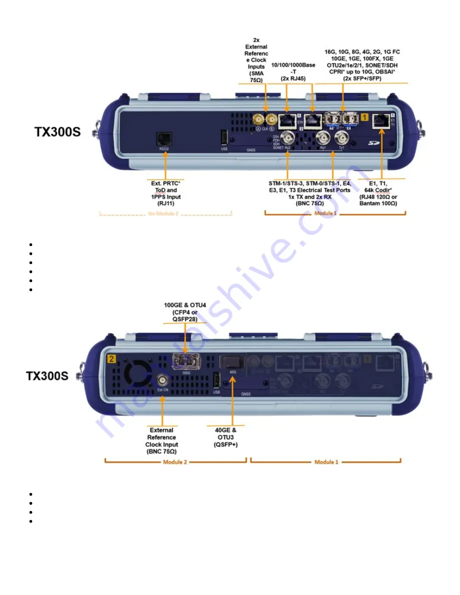
One 100G Module


Available with CFP4 or QSFP28 for 100GE and OTU4 applications

Supports IEEE 802.3bj Clause 91RS-FEC as required for SR4 (QSFP28)

QSFP+ for 40GE, OTU3

External clock interface

150 ppm clock offset generation

Soft LED indicators

OTDR Module

Fiber Optics, Transport and Service Verification, Testing & Troubleshooting

OTDR: Standard (+7dBm), High-power (+23 dBm) and PON (+23 dBm) versions

OTDR, OPM and VFL ports with interchangeable optical bulkhead connectors

This factory-installed option can be combined with any of the multi-service modules

TX300s_Platform_Manual_RevB00

Page 14 of 104

Summary of Contents for TX300s

Page 1: ......

Page 2: ...tions 3 5 Home Screen 3 6 Quick Access Menu 4 0 Getting Started 4 1 Initial Settings 4 1 1 Change language and user interface style 4 1 2 Change the time zone and current time 4 1 3 Change other setti...

Page 3: ...5 Software Upgrade 6 0 File Manager 6 1 File Manager Working with Saved Results Profiles Images 6 2 USB Memory Browser 6 3 Manage SD Card 7 0 Tools 7 1 IP Tools 7 2 Net Wiz 7 3 WiFi Wiz 7 4 ARP Wiz 7...

Page 4: ...7 6 Web Browser 8 0 Warranty and Software 9 0 Certification and Declarations 10 0 About VeEX Go back to TOC TX300s_Platform_Manual_RevB00 Page 4 of 104...

Page 5: ...sion from VeEX Inc This device uses software either developed by VeEX Inc or licensed by VeEX Inc from third parties The software is confidential and proprietary of VeEX Inc The software is protected...

Page 6: ...e The platform must be turned off and unplugged from VAC mains when removing or inserting test modules For safety and EMC Electromagnetic Compatibility empty module slots must be properly covered with...

Page 7: ...ion battery packs or products containing relatively large Li ion battery packs Electrical Connectors Telephone lines may carry dangerous voltages Always connect the electrical test ports to known tes...

Page 8: ...age up to four independent tests Flexible Software platform allows for the multiple test applications running simultaneously Multiple factory installed all inclusive hardware options including Single...

Page 9: ...unit The LED is off when the unit is powered off The LED is green when the unit is powered on The LED is orange when the unit is connected to the AC Mains and powered off charging Soft LEDs Each test...

Page 10: ...r use excessive pressure on the touch screen as this may damage its functionality Never use sharp objects such as a pen screwdriver etc as this may damage the surface Clean the surface of the touch sc...

Page 11: ...tery down without warning and test results may be lost Battery Safety precautions For more information on safety precautions for batteries see Lithium ion Battery Precautions Go back to TOC Battery Po...

Page 12: ...Universal multi service test modules offer OTN SDH SONET PDH DSn Carrier Ethernet MPLS Fibre Channel CPRI OBSAI Synchronization and more Additional Technologies Rates and Test Features can be added l...

Page 13: ...licenses Perfect companion to the OTDR hardware option One 340SM Module Single Port Group Flexible all in one multi service test solution from 64kbps to 16 Gbps can be combined with 100G and OTDR mod...

Page 14: ...50 ppm clock offset generation Soft LED indicators OTDR Module Fiber Optics Transport and Service Verification Testing Troubleshooting OTDR Standard 7dBm High power 23 dBm and PON 23 dBm versions OTDR...

Page 15: ...Go back to TOC 3 5 Home Screen Go back to TOC TX300s_Platform_Manual_RevB00 Page 15 of 104...

Page 16: ...on provides convenient and immediate access to system features connectivity accessories results etc Those features are always available independently of whether tests are running or not Go back to TOC...

Page 17: ...uration menus with access to detailed settings USA Provides simplified application based SONET DSn menu with more automation The Advanced Mode option displays the configuration menu for additional set...

Page 18: ...e the Test Cards icon on the top left corner of the screen to see a summary of all running tests available test resources switch to a different test touch on the status box with the magnifying glass i...

Page 19: ...t App ID Rate Technology Tap this button to release the Test App or change its Test Mode C Test Application Menu Lists all test Functions Applications and Tools available for the selected test mode Se...

Page 20: ...ngs Settings Menu Go back to TOC 5 1 1 About This section provides information about the software version serial number and MAC address of the management port of the unit as well as a list of software...

Page 21: ...activate new features tap on the expired item and enter the Activation Code that you received from VeEX VeEX partner or your manager Press Activate to complete the licensing process Each activation c...

Page 22: ...that have been tested and supplied by VeEX only to ensure compatibility and correct operation Bluetooth Setup Insert the Bluetooth adaptor into the USB port on the side of unit If you are using more t...

Page 23: ...e scanning is complete a list of discovered Bluetooth devices will be listed Please ensure the peripheral device is set to Discoverable during Scanning and Pairing operation Press Pair BT to begin the...

Page 24: ...tab Once paired click the Services button at the bottom of the screen to check the service attributes To upload test results via Bluetooth and Mobile phone to a UMTS or 3G network full data upload se...

Page 25: ...power and another for AC power The user has the option to select a timer to turn off the backlight if the unit is not in use This function helps improve the battery autonomy and preserve LCD life To e...

Page 26: ...nt system English feet or Metric meter Audible Alarm When enabled the test set s buzzer will sound beep when alarms and errors are being detected Show Password Hides unhides username and password info...

Page 27: ...agement Option Utility Settings Storage Setting Save Screen Settings Save Screen tab Helps control the behavior of the Lock key on the keypad The Lock key can be set to do the following Lock unlock th...

Page 28: ...ck to TOC 5 1 7 Date and Time This screen allows the user to set the date and time according to time zone or user requirement Daylight savings are automatically enabled in the utility Date Setup TX300...

Page 29: ...Time Zone Setup Go back to TOC TX300s_Platform_Manual_RevB00 Page 29 of 104...

Page 30: ...see the ReVeal RXT user manual on www veexinc com Remote access with VNC Server Viewer The test set VNC service can be managed in Utilities Settings More Remote Access menu to enable or disable the V...

Page 31: ...convert saved Test Profiles to PDF Manuals Access soft copies of the TX300s platform and modules manuals for quick reference Results Use this function to View Download Delete Filter and convert saved...

Page 32: ...rs who are only allowed to view the test set current screen via standard web browser clients but not make any changes to test or test set Type in the test set IP address in the web browser Click on vn...

Page 33: ...public IP addresses This VeEX hosted service and user interface take care of all the complex tasks required and present users with a simple application Connect online anytime anywhere with any comput...

Page 34: ...ary collaboration tasks It should not be used for long term applications VeEX offers other remote tools for long term applications Initiate an EZ Remote Session from the Test Set Not all VeEX test set...

Page 35: ...then both will share control over the unit Make sure the test set remains connected to the LAN WLAN Internet and that the EZ remote session indicator at the bottom of the screen stays green 6 When fi...

Page 36: ...ed since it is equivalent to having multiple users trying to operate one test set at the same time also known as mouse fight Nonetheless it may be effective for training purposes with one or two extra...

Page 37: ...rovided by physical buttons on the instrument such as Settings Home Save Test results Click or tap on the shortcut to activate it Once the remote GUI appears you can use the Remote Control tab to oper...

Page 38: ...st from the remote computer press the Save button below the screen image Then use the pop up keypad and or the PC keyboard to enter the file name and add any extra details if Advanced Save is enabled...

Page 39: ...st Result Files The Remote Platform Access tab provides links to access test results test profiles screen shots the user manual and other information stored in the test set TX300s_Platform_Manual_RevB...

Page 40: ...In this application the use of a local copy of the PDF file is reccommended as the PDF client in the local computer is most likely faster than accessing the remote one and may offer better tools and...

Page 41: ...e links provided or the respective F key on the computer s keyboard The screen capture function can be enabled in Utilities Settings Global Save Settings 5 1 10 VF Noise Calibration Microphone The tes...

Page 42: ...to an office The Noise Calibration function can be found in Utilities Settings More Noise Calibration Stay silent while the calibration is in progress If a headset is used for ISDN or VoIP calls it m...

Page 43: ...ity name in the search box City Location The unit connects automatically to the database here http www openstreetmap org Open Street map is similar to Google maps but the maps are open source and crea...

Page 44: ...rom a USB stick For further instruction on USB file transfer please see chapter 6 0 File Management Downloaded Map Maps are included if Advance Saving function is enabled Utilities Settings Global Sto...

Page 45: ...e report of the Wi Fi site survey results in HTML or PDF format QR code reader to document equipment bar code and serial numbers Camera function to document the AP location and installation GPS Coordi...

Page 46: ...so they all have accurate time The GPS receiver can be turned OFF if not used to save battery power A satellite table showing satellites in view satellites being used and signal to noise ratio is pro...

Page 47: ...at were not possible before This is called holdover mode Delay Compensation can be used to perform minor adjustments to the 1PPS phase to align it to a specific reference or to compensate for short ca...

Page 48: ...phase convergence graph Yellow dots indicate valid relative phase measurements output input Scattered yellow dots could indicate bad GPS signal which in turn provides bad timing accuracy or that the o...

Page 49: ...desired value Note that although the Sync 1PPS button could also be used to force alignment of the Atomic 1PPS output it does not adjust the required disciplining or steering parameters Using short T...

Page 50: ...used until its status shows Locked The atomic clock temperature and status can be monitored at Utilities Settings More High Precision Clock Source Atomic Clock The chip scale atomic clock is oven cont...

Page 51: ...ated to the operation of the test set and the measurements performed The user can access the table of contents and hyperlinks Use the scroll bars to navigate help content Help Menu Go back to TOC TX30...

Page 52: ...e time elapses no need to connect to the server Go back to TOC 5 3 1 Built in VeExpress Client Lets users connect to VeExpress Cloud directly from the test set from the field using any available inter...

Page 53: ...rade Procedure Full Version 1 Open the Software Upgrade tab Larger Full Upgrade package is shown if the test set has not been updated for a while when major new features are introduced or an OS update...

Page 54: ...ter field firmware update 2 Attach the DC charger to the test set 3 Confirm IP connection IP address 4 Check the new software version box 5 Tap on the Download button 1 Wait until the download process...

Page 55: ...IP connection established otherwise a reminder message will pop up Register 1 Enter the IP address of the server A test set must register to an R Server before it can upload results to the server 2 P...

Page 56: ...est set is authorized you can proceed to Upload Upload To upload result files to the R Server tap the Upload tab and select the desired files Tap on Upload or Upload Del Upload Transfers the selected...

Page 57: ...kage Download it from www veexinc com www v express com a link provided or by using the built in VeExpress client Unzip the file and copy to the root of a FAT32 USB memory stick if necessary 2 Insert...

Page 58: ...he files and copy to the root of a FAT32 USB memory stick if necessary 2 Insert the memory stick to the USB port located on the left side of the unit 3 Initiate Software Upgrade process Open the Utili...

Page 59: ...ap on any column header to sort by that specific parameter Tap again to change the sorting order The U L button lock and unlock files to prevent accidental deletion PDF button converts all selected fi...

Page 60: ...displayed Activate Filters Use the stylus to tap on the Y icon Check mark the desired attributes Filters parameters can be combined Reset Filters Press the Show All button Sorting Tap on a header to s...

Page 61: ...r folder in the file tree hierarchy The current folder structure is shown in the top bar Open Opens certain file types The USB tool supports one USB memory stick It shows the first memory stick that i...

Page 62: ...tion if the Data partition is nearly full The Format function is exclusively a maintenance tool Use ONLY when instructed by a VeEX Customer Care representative It erases all the information stored in...

Page 63: ...he unit will obtain IP address parameters from the DHCP server Gateway and DNS Enable or Disable Enabled If enabled enter the IPv4 address of the Gateway and DNS server in Static mode or use the IP ad...

Page 64: ...s are entered correctly Verify that the Ethernet cable is properly connected on the management port DHCP PASS indicates that an IP address has successfully been assigned IP PASS indicates that the IP...

Page 65: ...ec Use the alphanumeric keypad to enter the Ping repetition rate Ping second up to 10 pings per second Time Out Time to Live TTL in milliseconds Use the alphanumeric keypad to enter the maximum time a...

Page 66: ...e setup tab The following setup selections are available Profile Delete Save Save as Default Select Default to recall a trace route file or create a new test Destination Enter the IP address or URL of...

Page 67: ...e TTL Time to reach each router on the route Address Address of each router on the route If there is no response from a particular hop an asterisk will be displayed Trace Route Result Go back to TOC T...

Page 68: ...the desired IP range using the numeric keypad Select the test by placing a check mark in the corresponding box of any of the following ARP Ping Net Wiz Setup Go back to TOC 7 2 2 Net Wiz Results Summa...

Page 69: ...number of devices found Number of devices Routers Servers Hosts Net Wiz Results Devices Global Detail displays the Attribute MAC and IP Addresses and Ping test results of each device discovered Net Wi...

Page 70: ...PA WPA2 Encryption Scanning SSID broadcasting and report Signal Strength IP Connection and Ping Test Go back to TOC 7 3 1 WiFi Procedure Plug the WiFi adaptor into the USB port Allow at least 30 45 se...

Page 71: ...nnect to the web or preform the Ping test Once selected an Edit Settings function button appears on the right hand side bar Tap on Edit Settings or Connect AP to change the Encryption Type and enter t...

Page 72: ...ab displays the following information on the connection Connection Status ESSiD Name connected to BSSiD MAC address of wireless router device connected to Channel WiFi Channel connected to Encryption...

Page 73: ...ter a successful connection to the Access Point press Connect IP to obtain an IP address and access the additional IP tests like Ping Trace Route etc WiFi Wiz Connect IP Go back to TOC TX300s_Platform...

Page 74: ...e Save or Save As Start IP Starting IP Address End IP Ending IP Address Time Out s Range from 1 99 seconds Input using the numeric keypad Press Start The test will continue to run until the user press...

Page 75: ...ARP Wiz Result Go back to TOC TX300s_Platform_Manual_RevB00 Page 75 of 104...

Page 76: ...for Testing Optical Fiber Cabling specifies visual standards for connector end face inspection with a fiber microscope The ISO related standards and general industry practices recommend the following...

Page 77: ...d to replace existing scopes like DI 1000 with a more expensive ones It s a simple software option upgrade to the test set Much faster focus acquisition and analysis compared to slow electro mechanica...

Page 78: ...in focus image before automatically freezing the image and starting an analysis Select Never if manual capture or real time analysis is desired Auto freeze comes handy when both hands are tied e g one...

Page 79: ...the area calculation of the Pass Fail results they are just the operator s choice Save The Save button appears after freezing an image It performs the same action as tapping on the screen to save the...

Page 80: ...his soft button opens a more detailed analysis and report generation Use the check boxes to select the images to be analyzed Image File shows the name of the picture currently being displayed Use the...

Page 81: ...ts Table Shows the defects and scratches count by sizes and position used for the evaluation of the Pass Fail criteria according to the IEC 61300 3 35 standard TX300s_Platform_Manual_RevB00 Page 81 of...

Page 82: ...st set reports the difference in power readings between the Laser Source LS output being used and what is currently present at the connector after being attenuated by the fiber The results are present...

Page 83: ...against cable specifications In this case enter the length of the cable under test for the test set to make the conversion Go back to TOC 7 5 3 WiFi Spectrum Analyzer WiFi SA is a portable spectrum a...

Page 84: ...ireless frequency Topographic view Emphasizes which frequencies are the busiest across the entire spectrum Spectral view Historical view of wireless spectrum use at a point in time WiFi SA Planar View...

Page 85: ...running will give a good indication of the typical local network conditions WiFi SA Spectral View Spectral View Waterfall type view across the whole band graphs amplitude levels over time Uses color t...

Page 86: ...n Select a device in the sidebar and click the pattern in the Topographic view to identify a device WiFi SA Inspector Inspector The Inspector button setup allows the user to measure the frequency of t...

Page 87: ...is button allows the user to select frequency band for testing Go back to TOC 7 5 4 Data Card To establish an IP connection using a data card please make sure that the data card is connected on the US...

Page 88: ...ect the configuration parameters then press Connect Once a connection has been established The D for Data in the icon turns green The connection details are displayed in the IP Tools Status tab shown...

Page 89: ...sults for both frequency bands and also for graphical presentation of results for both 2 Tap the Scan button on the right side of the screen After the scan is completed the unit displays the list of a...

Page 90: ...specifications 3 Use the 2 4GHz GraphCH and 5 0GraphCH tabs to view the number of Access Points detected for each channel in the 2 4GHz and 5GHz bands and the strength of the strongest AP s signal for...

Page 91: ...ering full featured OTDR functionality For more information about OTDR functions see the OTDR Series V300 RXT FX100 MTTplus User Manual on www veexinc com 7 5 7 GNSS Operation GNSS Receiver Settings a...

Page 92: ...hat it has switched into Timing Mode 9 At this point the GPS Module should be providing accurate Time and Timing 1PPS 10 Tap the Sync ToD button to synchronize the test set s system real time clock At...

Page 93: ...he relative phase error until it becomes a horizontal line close to 0ns The time required for this may vary it should take less than 15 minutes 9 Close the Phase Graph and set the Time Constant s 900...

Page 94: ...50ns grid and estimate how dispersed the 1PPS samples are in ns then use a larger value as a threshold A vertical variation of 30ns is OK Clock Disciplining Using External 1PPS from a PRTC Cs or Rb Th...

Page 95: ...old ns 20 7 Verify that Disciplining Status Acquiring 8 Tap on the Phase Graph to monitor the relative phase error until it becomes a horizontal line at about 0ns 9 Close the Phase Graph and wait unti...

Page 96: ...pending on their elevation angles obstructions reflections and other factors To track this you need a tool that records the C No of every satellite as they pass by the antenna s aperture field of view...

Page 97: ...ce As the signal quality degrade even more they turn orange and red The example below shows the correlation between the sky view map and a map of the area around the antenna 7 5 8 GNSS Sky View 1 Go t...

Page 98: ...GNSS Setup 7 Tap on the Arrow to open the menu and tap on Start GNSS Start Menu TX300s_Platform_Manual_RevB00 Page 98 of 104...

Page 99: ...GNSS Start GNSS Results 1 To save Results to USB tap on the Arrow and then tap on Save Results To USB TX300s_Platform_Manual_RevB00 Page 99 of 104...

Page 100: ...GNSS Save Results Go back to TOC TX300s_Platform_Manual_RevB00 Page 100 of 104...

Page 101: ...ivity The built in web browser uses the management port IP connection An active IP connection can be established either through Ethernet WiFi or datacard ports The web browser defaults to VeEX s websi...

Page 102: ...c by the customer along with proof of purchase within thirty 30 days of the request by the customer freight prepaid Additionally during the warranty period VeEX Inc will provide without charge to the...

Page 103: ...e Association EFTA EN61010 1 For a copy of the CE Declaration of Conformity relating to VeEX products please contact VeEX customer service What is RoHS RoHS is the acronym for Restriction of Hazardous...

Page 104: ...service turn up and integrate service verification features across DSL Fiber Optics CATV DOCSIS Mobile backhaul and fronthaul CPRI OBSAI next generation Transport Network Fibre Channel Carrier Metro...

Reviews: