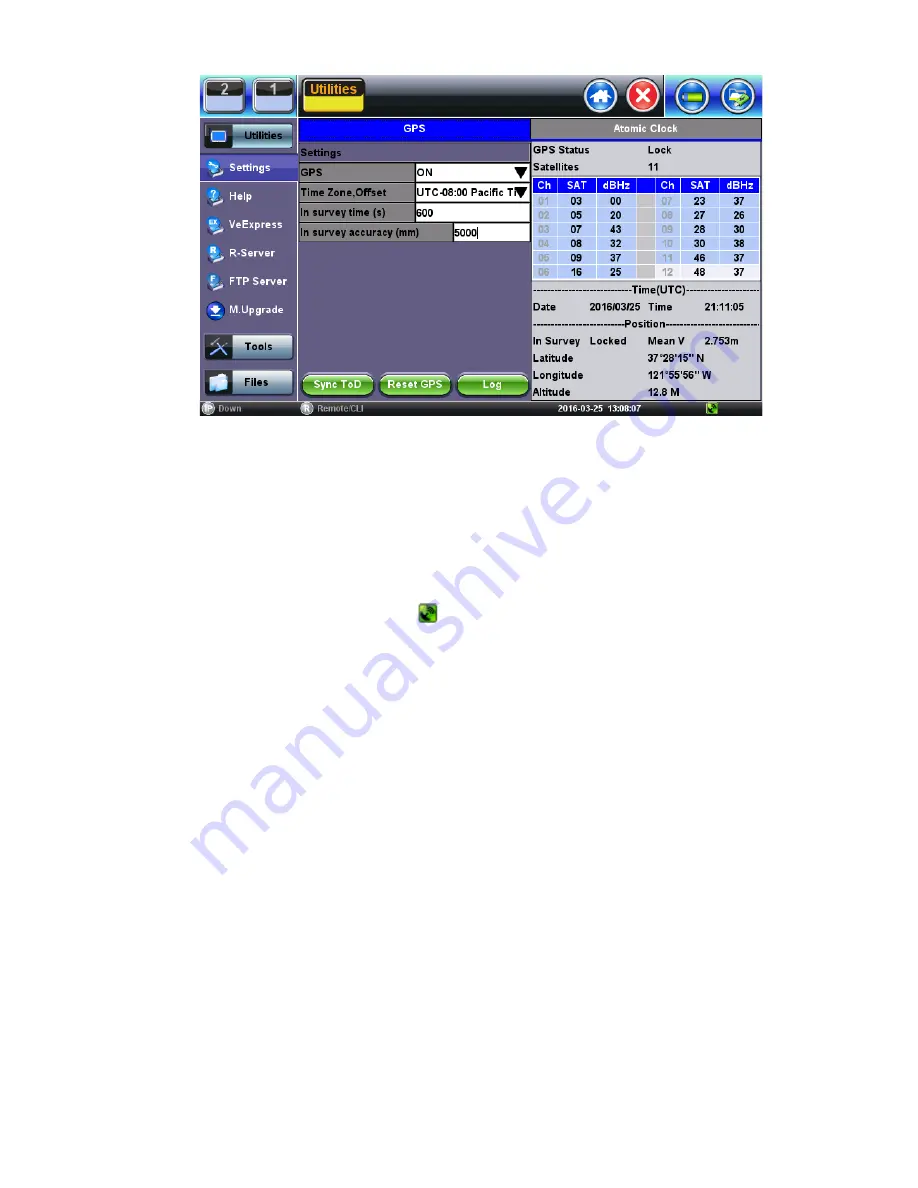
GNSS Receiver On
1. Turn the
GNSS Receiver = ON.
2. Set the
Satellite System = GPS
3. Set
In-survey time (s) = 600,
which is the time window used by the GNSS Receiver to assess stable location, using the
specified accuracy (below). Having an accurate tri-dimensional location is required to calculate accurate time.
4. Set
In-survey accuracy (m) = 5,
which is a target of <5m for the Mean V accuracy reading. Smaller values tighten the
location accuracy requirements, but the site survey process may take longer. It is possible to get better than 1.5m location
accuracy when using professionally-installed roof-top antennas.
5. Enter any antenna cable delay that needs to be compensated for (velocity of propagation is cable dependent, their values are
around 5ns/m or 1.2ns/ft). Enter 2
0ns if
using the 5m portable antenna.
6. Select the
Time Zone Offset
(it is used to calculate the local time of day).
7. Wait for GPS Status on top to show Lock and for the icon at the bottom of the screen to turn green. It indicates that it is
successfully tracking enough GPS and GLONASS satellites.
8. Wait for about 15 to 30 minutes for the
Mean V
value to be below
5.00m
and until the
In Survey
status also shows
Locked
.
This indicates that the GPS position has reached the required accuracy (site survey finished) and that it has switched into
Timing Mode.
9. At this point, the GPS Module should be providing accurate Time and Timing (1PPS).
10. Tap the
Sync ToD
button to synchronize the test set’s (system) real-time clock.
Atomic Clock Settings and Operation
This section explains the different disciplining parameters for the optional chip-scale Atomic Clock and provides the settings required
to quickly verify its proper operation. For application-oriented configurations, please refer to the suggested configurations table at the
end of this document.
Free Running Stage (Frequency only)
By default, the built-in Atomic Clock oscillator starts in free-running mode, providing a calibrated Atomic 10MHz frequency reference.
(Its exact frequency could vary over time due to ageing, temperature, storage and other factors.) It also produces an arbitrary (non-
traceable) 1PPS timing signal that is not aligned to the standard UTC second. Disciplining must be used in order to make the
necessary frequency and timing corrections.
Oscillator Disciplining Process (Frequency & Phase)
The disciplining process acts as a continuous “soft calibration” that corrects any frequency deviation in the oscillator and aligns the
timing pulse (1PPS) to the standard UTC second. The chip-scale atomic oscillator can be disciplined by:
1. The built-in precision GNSS Receiver (GNSS 1PPS).
2. An external traceable 1PPS signal from a primary reference time clock (PRTC) or time standard (Cs or Rb).
TX300s_Platform_Manual_RevB00
Page 92 of 104
Summary of Contents for TX300s
Page 1: ......
Page 15: ...Go back to TOC 3 5 Home Screen Go back to TOC TX300s_Platform_Manual_RevB00 Page 15 of 104...
Page 29: ...Time Zone Setup Go back to TOC TX300s_Platform_Manual_RevB00 Page 29 of 104...
Page 75: ...ARP Wiz Result Go back to TOC TX300s_Platform_Manual_RevB00 Page 75 of 104...
Page 100: ...GNSS Save Results Go back to TOC TX300s_Platform_Manual_RevB00 Page 100 of 104...


