
Assembly
5
________________________________________________________________________________________
_______________________________________
5
-
10
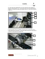
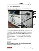
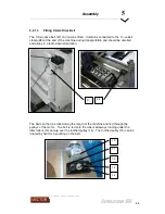
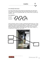
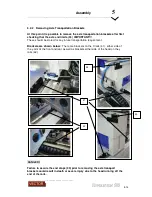
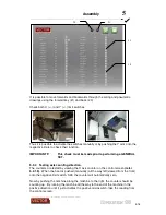
5.2.1.7 Fitting the Emergency Stop Pullwire
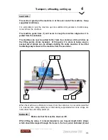
The emergency stop pullwire brackets must be fitted to each corner of the machine
and the pullwire strung around and tensioned so that the switch locks when the reset
button is pushed as indicated by a green band through the indicator lens.
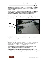
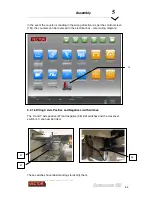
NOTICE:
The pullwire extends all the way around the machine and
connects back onto the plate which supports the switch mechanism. Ensure
the wire is sitting correctly in each pulley and test the operation.
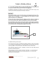
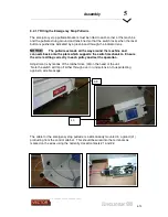
Adjustment is by means of the ratchet drive (40)on the head of the unit.
`Note the switch will trip off either through over or under-tension, thus protecting
against a wire breakage.
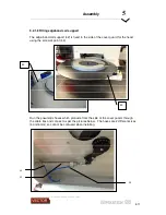
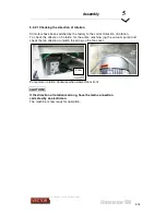
The cable for the emergency stop pullwire is inside already mounted in a gland (41)
protruding from the control cabinet. This should be wired into the terminals as
marked on the wires using the normally closed contacts 21 and 22.
39
40
Summary of Contents for Revolution 180
Page 1: ...Operating Manual...


