


Assembly
5
________________________________________________________________________________________
_______________________________________
5
-
2
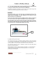
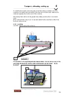
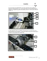
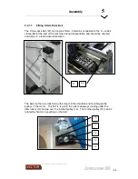
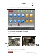
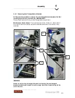
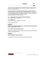
The unit is bolted up underneath the Y arm rear upright (15) and is pushed up
against the adjusting points (16). This has been factory set and should require no
adjustment for alignment provided the adjusting screws are touching their reference
surface (17).
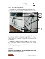
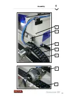
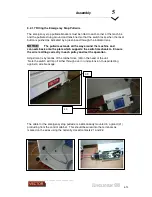
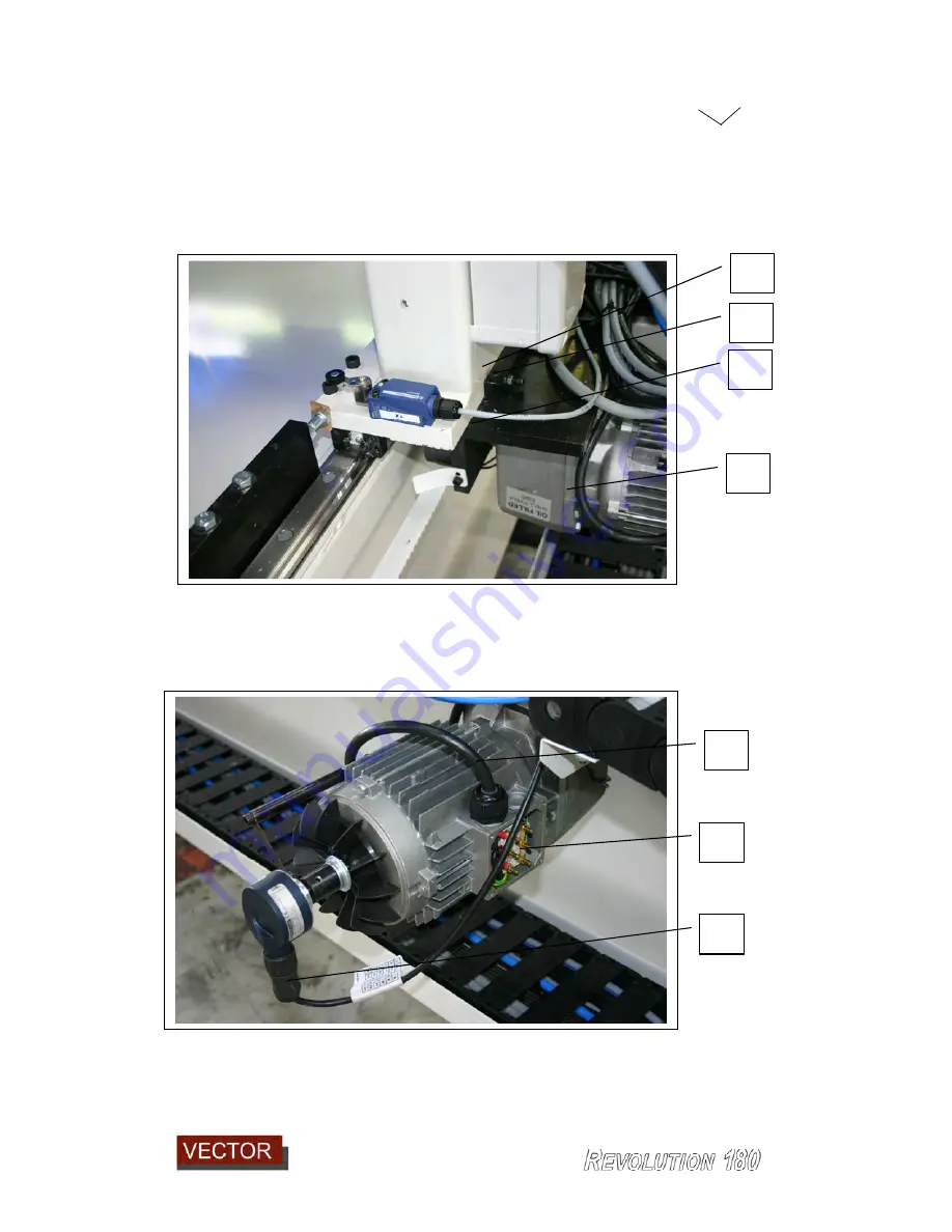
A cable marked A-X (18) is connected to the drive motor (10) (each wire core is
marked with the terminal number). The Encoder cable and plug (19) should also be
connected to the encoder and screwed tight.
16
15
10
17
10
18
19
Summary of Contents for Revolution 180
Page 1: ...Operating Manual...


