


Run
9
________________________________________________________________________________________
_______________________________________
9
-
52
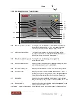
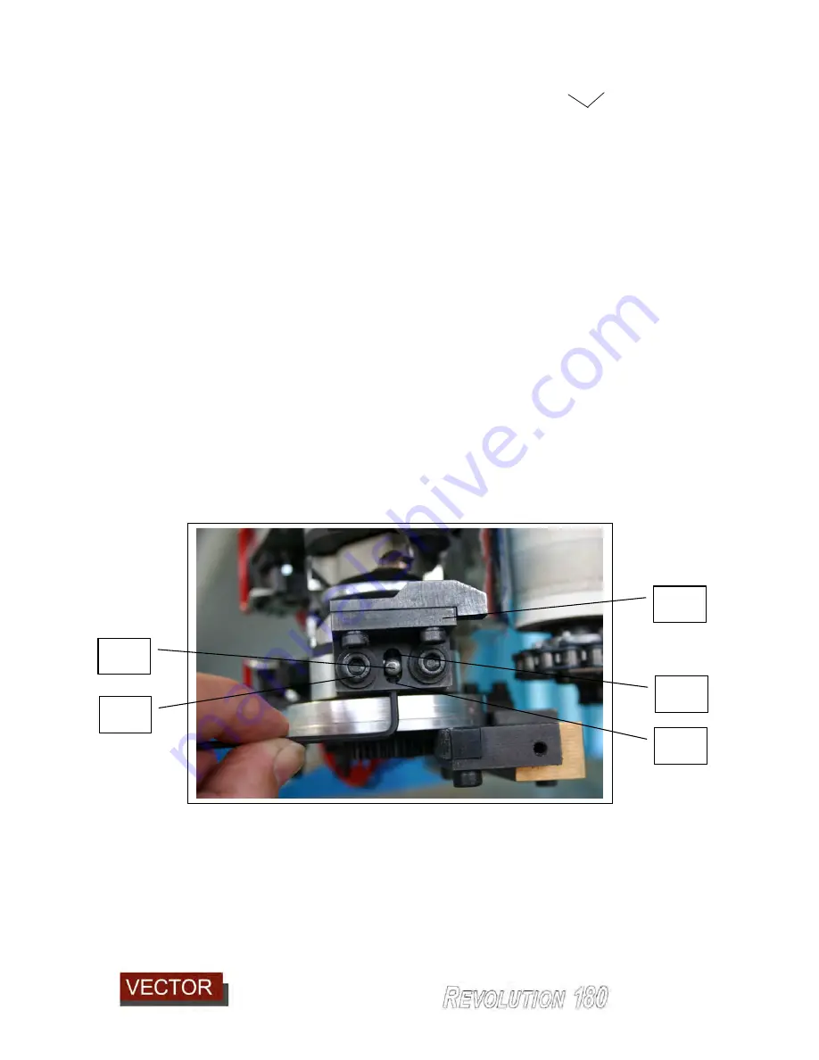
There are 2 locking screws (990) on each block, one fixed pin (992) and an upper (991)
and lower (993) adjusting screw. The shoe is restrained from tilting by a machined tongue
and groove arrangement on their mating faces.
Firstly release the locking screws (990) and then finger tighten them so they provide some
resistance to movement.
Now release the set screw which is resisting movement in the direction which you wish to
move the shoe. For example, if you wish to move the top shoe upward, release the screw
(993) by the amount you wish to move the shoe.
These set screws are M5 x 0.8mm pitch. Thus one full turn amounts to 0.8mm. A ¼ turn
amounts to 0.2mm.
Now tighten the top set screw (991) which will pull the vertical shoe upward until the lower
set screw (993) makes contact again with the fixed pin (992).
Lock the screws (990) on the shoe.
For the lower cutter block the same principal applies although the directions are
reversed.
For example to raise the tracer shoe (exposing less cutter) so that the cutter removes less
material, then release screw (991) the desired amount and pull the shoe up with screw
(993). Re-lock locking screws (990) as per procedure for top cutter block.
When you have completed reading the manual and are ready to run, it is possible to
perform a single panel test to set the trimmers.
It may be convenient to bring the trimmers together when making adjustments. This may
give better access to the adjusting screws and also allow a measuring calliper to measure
the spacing between the tracer shoes for reference. From this it is possible to measure
the adjustment changes made.
930
990
992
993
991
Summary of Contents for Revolution 180
Page 1: ...Operating Manual...