VCS VideoJet X.21 Manual Download Page 29

Quick Installation Guide

31

VideoJet X.21/G.703

 Manual

Step 2: Connecting to the
X.21 Transmission line

To connect the 

VideoJet X.21

 as a DTE (data terminal equip-

ment) to a DCE (data circuit-terminating equipment) use the deliv-
ered 15-pole SUB-D connection cable.

F

Plug this cable into the socket labelled “X.21“at the rear side of the 
unit. 

F

Connect the other end of the cable directly with the DCE (data ter-
minal equipment).

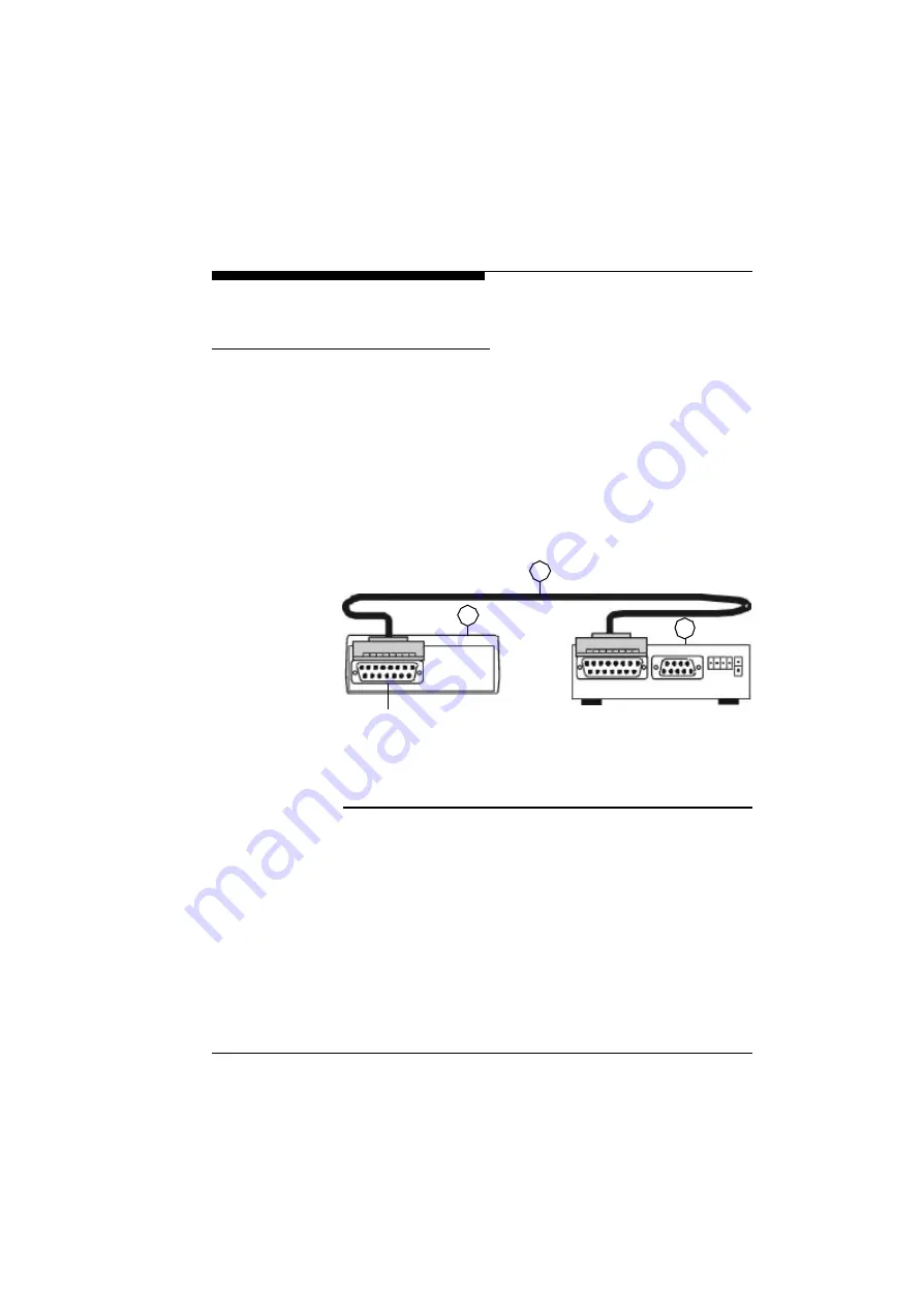
A correct connection is shown in Fig. 3-2 below:

(1) X.21DCE Adapter (data circuit-terminating equipment)

(2) 15-pole SUB-D connection cable for X.21 interface

(3)

VideoJet

xs

 transmitter or 

VideoJet

x e

 receiver

Fig. 3-2

Connecting to the X.21 transmission line

2

1

3

X.21 Interface

Summary of Contents for VideoJet X.21

Page 1: ...X 21 G 703 VideoJet VideoJet Manual...

Page 2: ...unication Systems GmbH Disclaimer This manual has been validated and reviewed for accuracy The included sets of descriptions were accurate at the time of this man ual s production However succeeding p...

Page 3: ...Chapter 3 Quick Installation Guide 29 Step 1 Connecting a Camera or Monitor 30 Step 2 Connecting to the X 21 Transmission Line 31 Step 2 Connecting to the G 703 Transmission Line 32 Step 3 Connecting...

Page 4: ...CTerminal 50 Audio and Video Settings 51 Audio Settings 52 Video Settings 54 Alarm Configuration 55 Alarm Stamping 55 Alarm Input Activation 56 Motion Detection 57 Checklist for Activating Motion Dete...

Page 5: ...sical Specification 74 Environmental Specification 74 Electromagnetic Emmissions and Safety 75 Chapter 8 Troubleshooting 77 General Service Remarks 77 Basic Functioning 78 Power LED 78 Terminal Progra...

Page 6: ...Contents 8 VideoJet X 21 G 703 Manual...

Page 7: ...ecting Power to the X 21 Interface 33 Fig 3 5 Connecting Power to the G 703 Interface 33 Fig 4 1 Pin Assignment 36 Fig 4 2 Pin Assignment of the I O Connector 39 Fig 4 3 Connection Scheme for the X 21...

Page 8: ...Figures 10 VideoJet X 21 G 703 Manual Fig 5 8 Camera Configuration 62 Fig 5 9 Interface Configuration 64 Fig 5 10 Common Configuration 66...

Page 9: ...11 VideoJet X 21 G 703Manual Tables Tab 5 1 Connection Status Display 49 Tab 5 2 Status Display for Signal Input and Relay Output 50 Tab 5 3 Audio Coding Method 52 Tab 5 4 Activation Display 56...

Page 10: ...Tables 12 VideoJet X 21 G 703 Manual...

Page 11: ...21 G 703 allows for transport of video accompa nying audio optional and data over a standardized and leased X 21 G 703 transmission line Purpose of this Manual This manual describes the features of t...

Page 12: ...formation required Wherever this symbol appears certain information is required for correct configuration and operation Eventually you need to talk to users manufacturers of connected equipment or a s...

Page 13: ...er typed string enter without double quotes Initial Caps Menu titles and window and button names Enter Named keys in text are shown enclosed in square brackets The notation Enter is used for the Enter...

Page 14: ...Preface 16 VideoJet X 21 G 703 Manual...

Page 15: ...ry A terminal pro gram is supplied for additional configuring VideoJet G 703 only has to be connected to the DCE terminat ing adapter DCE data circuit terminating equipment of the G 703 interface The...

Page 16: ...stem was designed to enable multimedia data streams over an existing X 21 G 703 leased line It combines state of the art compression technology with ease of use enabling you to transmit full colour li...

Page 17: ...nitor on the receiving end of the X 21 G 703 leased connection Remote control of peripheral components like pan tilt zoom cameras is facil itated by the bidirectional serial interface With the audio o...

Page 18: ...eo surveillance and security The integrated motion video sensor will set up a connection autonomously when motion in the scene is detected Pre alarm history is stored in a video ring buffer for alarm...

Page 19: ...l Automatic and dynamic adaptation to the transmission speed of the X 21 port between 64 Kbit s to 2 048 Mbit s l Constant transmission speed of the G 703 port of 2 048 Mbit s E1 l Compact autonomous...

Page 20: ...and Interfaces Fig 2 3 VideoJet G 703 System Concept and Interfaces Camera VideoJet X 21 Monitor X 21 leased line DTE Control Input Control Output Serial Interface alternative Camera VideoJet G 703 Mo...

Page 21: ...VideoJetXEA GEA unit with audio option l AC plug power adapter 5V DC output l 2 m long 15 pole connecting cable for the X 21 interface l RJ45 ISDN cable for connection to the G 703 interface l 3 m co...

Page 22: ...nel The front panel connectors are dedicated to the media interfaces i e video audio and data and are depicted in Fig 2 4 1 Green Power LED blinking when connected to another Vid eoJet X 21 G 703 unit...

Page 23: ...ct connection of a telephone handset Note that the audio connectors 3 4 and 5 are only functional for units equipped with the optional audio interface The model name is appended by the letter A for au...

Page 24: ...32 3 Signalling input and relay output 4 Power connector for connecting the AC plug power adapter Fig 2 5 VideoJet X 21 Rear Panel Connectors The power LED on the VideoJet X 21 is the only display tha...

Page 25: ...nformation If the LED is on the ISDN port is properly connected to the ISDN net work The yellow TX Transmit LED will blink for each packet being trans mitted Note that packet reception is not signalle...

Page 26: ...pheral devices to the VideoJet X 21 G 703 unit Note Use only the supplied AC plug power adapter If the adapter the cable or the connector show any sign of damage do not use the power adapter and send...

Page 27: ...29 VideoJet X 21 G 703Manual Quick Installation Guide 3 For the fastest route to get your product up and running just follow the next 4 steps below...

Page 28: ...used F In order to connect a monitor to the VideoJetXE GE receiver use a standard coaxial cable and plug it into the BNC connector at the front side of the unit Any PAL or NTSC video monitor can be u...

Page 29: ...nection cable F Plug this cable into the socket labelled X 21 at the rear side of the unit F Connect the other end of the cable directly with the DCE data ter minal equipment A correct connection is s...

Page 30: ...ection cable F Plug this cable into the socket labelled G 703 at the rear side of the unit F Connect the other end of the cable directly with the DCE data ter minal equipment A correct connection is s...

Page 31: ...tablished to the remote end the power LED blinks Live video images are transmitted immediately 1 X 21 DCE adapter data circuit terminating equipment 2 15 pole SUB D connection cable for X 21 interface...

Page 32: ...the X 21 G 703 leased line The X 21 G 703 leased line and the transmission line must be set up and switched through On most terminal adapters where DCEs are used as the termination of the X 21 G 703...

Page 33: ...ndard PAL or NTSC When using VCRs as input source the video quality can be improved by setting theInput Source in the Video Configu ration Page see Chapter 5 to VCR The video input is equipped with an...

Page 34: ...at the front panel of the VideoJet X 21 G 703 In order to select this audio interface check the radio button labelled Handset in the Audio Configuration Page F To select this audio port check the sett...

Page 35: ...erchangeably The functions of the terminal port and the transparent data port can be interchanged Terminal Port For local control and configuration of theVideoJet X 21 G 703 unit a data terminal e g a...

Page 36: ...n addition this channel can be used for remote control of any external device with a serial interface The serial data is transferred in parallel to the video and audio data The following interface par...

Page 37: ...I O Connector The input is activated by connecting pin1 to pin 2 Triggering of an alarm may be configured to occur upon closing active high or opening active low the contact between pin 1 and pin 2 I...

Page 38: ...r of interface X 21 to the VideoJet X 21 F Connect the other end of the connecting cable to port of the DCE X 21 TA data circuit terminating equipment Once the VideoJet X 21has been connected to the t...

Page 39: ...f live video images is only possible if a DCE data circuit terminating equipment is installed at both ends of the X 21 G 703 leased line The X 21 G 703 leased line and the transmission line must be se...

Page 40: ...gnment of the X 21 Socket on VideoJet X 21 Some of these signals are optional However the following are mandatory l Transmit T a and T b l Receive R a and R b l Clock S a and S b Pin Function to X 27...

Page 41: ...to the transmis sion line it can be connected to the power supply unit Only use the power supply unit included in the scope of supply The G 703 port of the VideoJet G 703 supplies differential sig na...

Page 42: ...ges is only possible if a DCE data circuit terminating equipment is installed at both ends of the G 703 leased line The G 703 leased line and the transmission line must be set up and switched through...

Page 43: ...ing theNCTerminal terminal program contained in the scope of supply of the Vid eoJet X 21 G 703 The NCTerminal software allows configuration and control of the VideoJet X 21 G 703 unit even if no conn...

Page 44: ...on the new icon or start the program from the file manager or the Windows Explorer When the software is started up the field Local device changes to yellow as soon as aVideoJet X 21 G 703 device has b...

Page 45: ...Configuration with the NCTerminal Software 47 VideoJet X 21 G 703Manual Fig 5 1 Configuration of the COM Port...

Page 46: ...g 5 2 Status Display of NCTerminal The main window ofNCTerminal is subdivided into three sections The top section displays the connection status In the central sec tion you can access the configuratio...

Page 47: ...he field Remote Unit is displayed red and you can click on it to check and configure the remote VideoJet X 21 G 703 The display next to field M shows the status of the X 21 G 703 con nection Tab 5 1 C...

Page 48: ...1 G 703 Devices with NCTerminal By clicking on the icons of the devices you can configure and oper ate the local and remote units both locally and remotely The set tings are made on various setting pa...

Page 49: ...s stored in the device the video audio page is mainly used to control the connected VideoJet X 21 G 703 device With the exception of the audio setting for connection and selection of the audio source...

Page 50: ...y lower frame rate and or reduced image res olution VideoJet X 21 G 703 offers several configuration options to provide the optimum solution for each application which are described below Various codi...

Page 51: ...ttings you make are stored in the non volatile mem ory of the device Audio transmission can be switched on and off for both transmis sion directions independently You can also configure whether the Vi...

Page 52: ...ht be suitable when the data rate is limited and or in certain circumstances a higher image refresh rate takes priority over a high local resolution You can switch from one mode to the other by clicki...

Page 53: ...G 703 unit on the Alarm inputs page Fig 5 5 Configuration of the Alarm Inputs Alarm Stamping In addition to the date time and name stamping on the video image described in later sections it is also p...

Page 54: ...triggered Input contact is used for connecting external detectors For the alarm contact you can set whether an alarm is to be triggered in a closed High active or closed Low active state You can assi...

Page 55: ...under the slider with which previous settings can be found again precisely The optimum setting for the Sensitivity slider can be found by experimenting It is important to remember that a higher sensi...

Page 56: ...local and or remote station the VideoJet X 21 G 703systems also feature the powerful option of automatic switching Fig 5 6 Configuration of the Output Action Events have been defined that automaticall...

Page 57: ...put of the remote end Alarm sources In addition to the alarm input mentioned above internal alarm sources video alarm motion detection are available for switching the outputs Example Connection of ext...

Page 58: ...on the buttons It is impor tant to remember that the status of the outputs is notstored When the device is switched on all outputs are in the idle state Individual switching responses are configured i...

Page 59: ...remote end a monostable switching response can be used to increase short input impulses This option can be used for sensors for example that only generate short impulses motion detectors glass breakag...

Page 60: ...03 Manual Camera Configuration On the Camera page of the configuration dialog you can set the display of the name and date time as well as the assignment of a name to the camera channel This is also w...

Page 61: ...ame The camera name is entered as already described for alarm inputs and outputs by direct entry into a field Again the name is stored in the non volatile memory and is also used for the camera button...

Page 62: ...d number of data and stop bits must be set to suit the requirements of the application in question If you click on the button Flip Camera and Modem Port you can exchange the functions of both the seri...

Page 63: ...er connected to a VideoJetXE GE receiver For transparent data transmission between each of the camera ports mode Transparent 1 must be selected Unlike transparent mode 1 with Transparent 2 the binary...

Page 64: ...nfiguration The dialog page General settings contains the settings of some of the basic elements of theVideoJet X 21 G 703 unit These include password protection setting the internal VideoJet X 21 G 7...

Page 65: ...together with the name of the camera separated by a colon in the live picture Device Number ID A number can be allocated for automatic identification of linked VideoJet X 21 G 703 devices which is rea...

Page 66: ...Configuration with the NCTerminal Software 68 VideoJet X 21 G 703 Manual...

Page 67: ...s possible on analog video cables simply by plugging into the X 21 G 703 leased line As X 21 G 703 leased lines provide a permanent and steady stream of data they are extremely suitable for digital vi...

Page 68: ...the motion detector can be selected in the same menu This parameter needs to be adapted to the requirements of the particular application The best setting should be determined experimentally The moti...

Page 69: ...elect the appropriate file with the latest firmware using the search button F Activate the button Upload F After about 30 60 seconds you should get a feedback message from the connected VideoJet unit...

Page 70: ...ete the green LED will stop blinking F Any attempt to upload an invalid firmware file will result in receiving the message upload failed F Once firmware has been successfully uploaded revisiting the p...

Page 71: ...coding G 711 G 728 Data communication and remote control H 224 X 21 Interface G 703 Interface 15 pole SUB D socket RJ45 socket 120 Ohms Video input VideoJetXS GS only BNC PAL NTSC 75 Ohms 1 Vss Video...

Page 72: ...specific adapters Europe default UK US AUS The physical adapter for the wall outlet is interchangeable for adap tation to different countries The adapter simply snaps into the plug power supply Conta...

Page 73: ...Technical Specification 75 VideoJet X 21 G 703Manual Electromagnetic Emmissions and Safety Meets requirements of EN 55103 1 EN 55103 2 EN 60950...

Page 74: ...Technical Specification 76 VideoJet X 21 G 703 Manual...

Page 75: ...In this case it is necessary to mention the serial number noted on the bottom of the unit and the firmware version General Service Remarks The user should resist the temptation to personally perform r...

Page 76: ...et l Check the voltage rate of 5 Volt from the power supply If it is correctly connected and the green power LED still does not light you have to exchange the power supply by a new one from your deale...

Page 77: ...8N1 should be programmed for the terminal program NCTerminal l If the data exchange between the terminal program NCTermi nal and the VideoJet X 21 G 703 still does not work check the serial cable Tro...

Page 78: ...cable and connect a video monitor to the camera in order to check that the latter is functioning correctly l If a video recorder is connected to theVideoJetXS GS sender set the video input source on...

Page 79: ...are set in the Audio Configuration pages of both systems i e select the appropri ate interface line I O or handset l Switch the coding mode to G 711 or G 728 l Select a non zero volume l After establi...

Page 80: ...Troubleshooting 82 VideoJet X 21 G 703 Manual...

Page 81: ...T H 224 Standardized protocol for data communication and remote control H 261 Standard motion video coding algorithm defined by ITU T ID Identification machine readable number or name IEEE Institute o...

Page 82: ...Glossary 84 VideoJet X 21 G 703 Manual...

Page 83: ...56 Alarm input 59 Alarm text display 56 Audio coding 73 Audio input 73 Audio level 52 Audio option 19 36 Audio output 73 Audio transmission 52 Automatic connection 69 B Bistable 60 Bit clock 40 79 BNC...

Page 84: ...vice name 63 67 E Establishing a connection 69 F Firmware upgrade 71 Flash EPROM 71 G G 703 data rate 17 73 G 703 port 17 19 21 23 43 44 73 H Handset interface 25 73 Handset interface pin assignment 3...

Page 85: ...9 50 Loop function 34 41 M Monostable 60 Motion detection 57 Motion detector 70 N NTSC 35 63 O Output actions 39 P PAL 35 63 Pan tilt zoom cameras 19 Port 26 36 Purpose of this Manual 13 R Realtime cl...

Page 86: ...8 Signalling devices 27 Switch output 58 Switching response 60 61 T Terminal program 17 26 46 Text display 62 63 Text insertion 55 Transmission speed 17 Transparent data transmission 65 Transparent da...

Page 87: ...Index 89 VideoJet X 21 G 703Manual X X 21 data rate 17 73 X 21 port 17 18 21 23 40 42 73...

Page 88: ...Index 90 VideoJet X 21 G 703 Manual...

Page 89: ...91 VideoJet X 21 G 703Manual...

Page 90: ...VCS Video Communication Systems GmbH Forchheimer Stra e 4 90425 N rnberg Germany Phone 49 911 93456 0 Fax 49 911 93456 66 http www vcs com ID Nr 7096 1299 0 1...

Reviews: