Installation, Operating & Maintenance Instructions
Series 650 DN 350 (I.D. 14”), CC-Link
VAT Vakuumventile AG, CH-9469 Haag, Switzerland
Tel +41 81 771 61 61 Fax +41 81 771 48 30 [email protected] www.vatvalve.com
286241EA
2010-10-11
57/86
3.12 CC-Link interface (Process data – cyclic communication)
The buffer naming is in view from customer (master) PLC.
Data format: All signals are transmitted and received in intel format (low byte first).
All one-byte signals use the least significant byte (LSB).
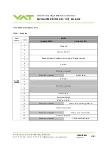
3.12.1 OUTPUT Buffer (Master PLC)
3.12.1.1 Overview
Buffer
Data
model
Index
Contents (MSB)
Contents (LSB)
0
1
Pressure setpoint
2
3
Position setpoint
4
5
6
7
8
9
Not used – reserved
10
Not used – reserved
Control mode setpoint
11
General control setpoint
12
13
14
15
Not used – reserved
16
17
Cluster valve freeze position setpoint
18
Not used – reserved
Cluster valve freeze address setpoint
19
Not used – reserved
Cluster valve freeze control setpoint
16 bit
(Word)
20
Not used – reserved
Cluster valve monitoring address setpoint
Note: For data consistency make sure your master PLC is supporting “block guarantee of cyclic data per station”.


