


Installation, Operating & Maintenance Instructions
Series 650 DN 350 (I.D. 14”), CC-Link
VAT Vakuumventile AG, CH-9469 Haag, Switzerland
Tel +41 81 771 61 61 Fax +41 81 771 48 30 [email protected] www.vatvalve.com
286241EA
2010-10-11
14/86
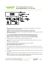
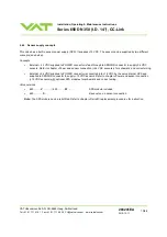
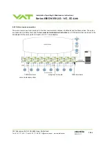
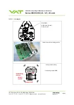
2.6.3 Power and sensor connection (
±
15 VDC sensors) using SPS module
[650 . . - . . V . - . . . . / 650 . . - . . W . - . . . . versions only]
Note:
•
Use shielded sensor cable(s). Keep cable as short as possible, but locate it away from noise sources.
•
Connect
the
±
15 VDC sensors at DB–15 female sensor connector exactly as shown in the drawing above. Do not
connect other pins that may damage sensor, power supply or controller!
•
Connector: Use only screws with 4-40UNC thread for fastening the connectors!
Pins 4 and 8 must be bridged for operation!
An optional switch would allow for motor interlock
to prevent valve from moving.


