Installation, Operating & Maintenance Instructions
Series 650 DN 350 (I.D. 14”), CC-Link
VAT Vakuumventile AG, CH-9469 Haag, Switzerland
Tel +41 81 771 61 61 Fax +41 81 771 48 30 [email protected] www.vatvalve.com
286241EA
2010-10-11
81/86
5.2 Option
board
The option board may or may not be equipped in your valve depending on the order. Refer to page 1 of this manual to
check valve version. This board includes the optional modules for the valve which are:
•
±15VDC sensor power supply (SPS)
•
Power failure option (PFO)
It is available in 3 versions. These are:
•
SPS module only
•
PFO module only
•
SPS and PFO module
The modules may be retrofitted or replaced easily. The battery lifetime of the PFO module depends on the ambient
temperature (see below). To assure PFO function the option board must be replaced after battery life has expired.
For ordering number of the modules refer to «Spare parts and accessories».
5.2.1 Durability of power fail battery
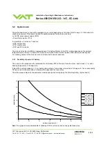
The curves in the graph show the estimated life of UltraCap PFO in the worst condition (max. sensor load = 1 A, valve
heating temperature = 150 degree C).
If the SPS is not fully loaded (< 1 A) or heating temperature of valve body is lower than 150 degree C, the corresponding
life time curve will be somewhere in between the upper and the lower curve.
Therefore please determine the equivalent maintenance period for replacing the UltraCap battery (Option board).
0
20
40
60
80
100
120
20
25
30
35
40
45
50
Ambient temperature [°C]
D
u
ra
bil
ity
[m
o
n
ths
]
w/o SPS module,
valve unheated
with SPS module,
valve unheated
w/o SPS module,
valve heated
with SPS module,
valve heated
Note: This graph shows estimated life of UltraCap PFO for reference and not as guaranteed value.


