


Installation, Operating & Maintenance Instructions
Series 650 DN 350 (I.D. 14”), CC-Link
VAT Vakuumventile AG, CH-9469 Haag, Switzerland
Tel +41 81 771 61 61 Fax +41 81 771 48 30 [email protected] www.vatvalve.com
286241EA
2010-10-11
80/86
D e s c r i p t i o n
Required tool
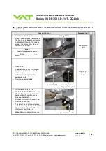
36. Turn on power of controller.
Note: valve moves to close position.
37. Open valve and install sealing ring
and pendulum plate in reverse order
as they had been disassembled
(steps 9 to3).
open end wrench
13mm
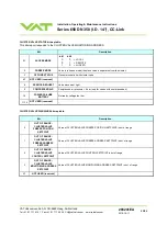
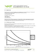
DN
Distance D [mm]
between bonnet
flange surface
and pendulum
plate.
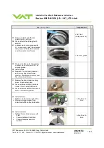
If actuator was replaced, proceed with
point 38, otherwise go to point 40.
38. Close valve and check if pendulum
plate is in center of flange. Check
can be done either visual or by
measurement.
When the valve is mounted to a tool,
the bonnet has to be removed and
the center position can be measured
by a depth gauge (see picture).
If the centering (or distance) is not
correct, proceed with point 39.
D
350
59.0 ±0.5
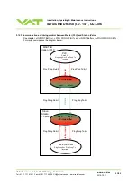
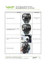
39. If necessary adjust pendulum plate:
a. Move pendulum plate a little towards
open (e.g. position 1% of full stroke)
b. Use adjustment screw at flange side
of actuator (1 turn clockwise adjusts
pendulum plate by about 3mm
towards open).
c.
Restart valve in menu
‘System/Recovery’
d. Check pendulum plate position
according point 38 and redo
adjustment procedure if necessary.
Adjusting screw mounted either in actuator
position «B1 standard» or «B2 option»
Allen wrench
2mm
40. Clean valve bonnet sealing surface
and o-ring
•
Mount valve bonnet, see step 2.
•
Tightening torques for bonnet
screws, see in table to the right.
Max. torque 16 Nm
Allen wrench
8mm


