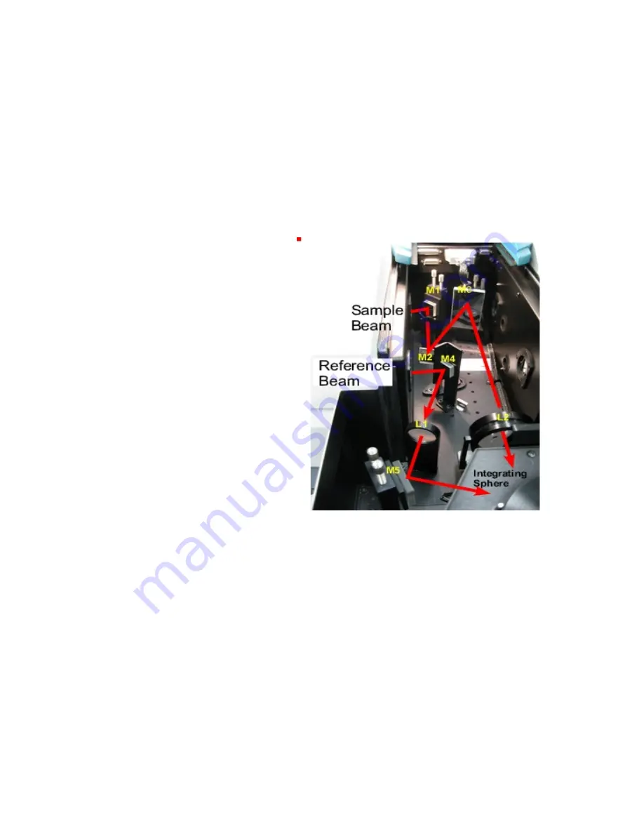
4
beam hits the center of mirror M3 then use M3 so the beam hits the center of the
sample. Some of the mirrors are more complicated to adjust (although these can
often be left alone). For help with alignment, talk to one of the GLAs and read
the alignment instructions, which can be found under Help.
Small samples
Most typical lab samples are smaller in size than what the instrument was designed to
measure. For all three types of measurements (T, C, and R), it is best to under fill the
sample area.
Spot size
- There are two ways of
reducing the beam spot size:
1)
Slit width:
The simplest way is
to reduce beam size is by the slit
width. Click on the
Setup
the
options
tab. Under slit height,
switch to Reduced. It takes about a
minute for the slit to change.
2)
Small spot kit:
There are also a
series of lenses that can be put in
the optical path to focus the beam
into a smaller spot on the sample.
Again there are three lenses with
different focal lengths and marked
T, C, and R for the three positions of
the integrating sphere. Also, the
large mirror (M3) is switched out
for a one with a different curvature;
this mirror is always kept in the T
position, regardless of the type of
measurement being made.
3) Aperture kit for reflection
measurements
For normal incidence reflection measurements, the open circle in the rear of the
integrating sphere is several inches in diameter. There are a series of apertures,
which have the white Spectralon material (same roughened Teflon that is inside the
integrating sphere), that can slide onto the slot on the back of the integrating sphere.
The spring-loaded mount that holds the sample against the integrating sphere first
needs to be taken off. Slide on the appropriate aperture and then either tape your
sample onto the back of the aperture, or put back on the spring-loaded sample
mount.
If the beam spot overfills the aperture, you can correct for this “stray light” by
performing a Zero/baseline Correction. Normally, the 0%TBaseline scan is run by
blocking the beam before it enters the integrating sphere, which accounts for
Figure 4 Photo of diffuse reflectance accessory with
beam path.


