2NM/2NX/2NY/2NZ/2P0/2P6
2-1-2
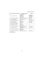
1. Control PWB (CONPWB)...................... Controls the software such as the print data processing and pro-
vides the interface with computers.
Controls printer hardware such as high voltage/bias output con-
trol, paper conveying system control, and fuser temperature con-
trol, etc.
2. Connect -Left PWB (C-LPWB).............. Consists of wiring relay circuit between control PWB and drum
connect PWB.
3. Connect-Right PWB (C-RPWB)............ Consists of wiring relay circuit between control PWB and power-
source PWB.
4. Operation panel PWB (OPPWB) *4 ...... Consists of wiring that relay circuit between control PWB and
right/left key PWB and LCD.
5. Key-Left PWB (K-LPWB) *4.................. Consists the LED indicators and key switches.
6. Key-Right PWB (K-RPWB) *4............... Consists the LED indicators and key switches.
7. High voltage PWB (HVPWB) ................ Generates main charging, developing bias, transfer bias and sep-
aration bias.
8. Power source PWB (PSPWB) .............. After full-wave rectification of AC power source input, switching
for converting to 24 V DC for output. Controls the fuser heater.
9. Drum PWB (DRPWB) ........................... Relays wirings from electrical components on the drum unit.
10. Drum connect PWB (DRCPWB) ........... Consists of wiring relay circuit between connect left PWB and the
drum unit.
11. Toner container PWB (TCONPWB) ...... Reads the container information.
12. Toner container connect PWB
(TCONCPWB)....................................... Consists of wiring relay circuit between control PWB and the
toner container.
13. CCD PWB (CCDPWB).......................... Reads the image of originals.
14. LED PWB (LEDPWB) ........................... Controls the LED.
15. APC PWB (APCPWB) .......................... Generates and controls the laser beam.
16. PD PWB (PDPWB) ............................... Controls horizontal synchronizing timing of laser beam.
17. Thermister connect PWB
(FTHCPWB).......................................... Consists of wiring relay circuit between fuser thermistor, fan motor
and the control PWB.
18. Operation panel PWB (OPPWB) *3 ...... Consists of wiring that relay circuit between control PWB and
LCD.
Summary of Contents for P-4030 MFP
Page 7: ...This page is intentionally left blank ...
Page 13: ...This page is intentionally left blank ...
Page 19: ...2NM 2NX 2NY 2NZ 2P0 2P6 5 Installation Guide PF 320 Paper Feeder ...
Page 55: ...2NM 2NX 2NY 2NZ 2P0 2P6 1 2 24 This page is intentionally left blank ...
Page 386: ...2NM 2NX 2NY 2NZ 2P0 2P6 1 5 100 This page is intentionally left blank ...
Page 486: ...Installation Guide PF 320 Paper Feeder Installation Guide ...
Page 487: ...PF 320 㾌㙼 㾌㙼 PF 320 PF 320 PF 320 㪧㪝㪄㪊㪉㪇 㪧㪝㪄㪊㪉㪇䈱 㪧㪝㪄㪊㪉㪇G 㾌 㾌 PF 320 PF 320 ...


