2NM/2NX/2NY/2NZ/2P0/2P6
1-5-54
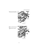
10. Remove the front right cover forward.
Figure 1-5-89
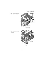
11. Remove three connectors, two FFCs
and two USB connectors from the Con-
trol PWB.
12. Remove three screws and grounding
terminal from the image scanner unit.
13. Remove it by sliding the image scanner
unit backward and then takeing upward.
Figure 1-5-90
Front right cover
Screw
Image scanner
unit
Main unit
Screw
Connectors
FFCs
USB
connectors
Screw
Grounding
terminal
Summary of Contents for P-4030 MFP
Page 7: ...This page is intentionally left blank ...
Page 13: ...This page is intentionally left blank ...
Page 19: ...2NM 2NX 2NY 2NZ 2P0 2P6 5 Installation Guide PF 320 Paper Feeder ...
Page 55: ...2NM 2NX 2NY 2NZ 2P0 2P6 1 2 24 This page is intentionally left blank ...
Page 386: ...2NM 2NX 2NY 2NZ 2P0 2P6 1 5 100 This page is intentionally left blank ...
Page 486: ...Installation Guide PF 320 Paper Feeder Installation Guide ...
Page 487: ...PF 320 㾌㙼 㾌㙼 PF 320 PF 320 PF 320 㪧㪝㪄㪊㪉㪇 㪧㪝㪄㪊㪉㪇䈱 㪧㪝㪄㪊㪉㪇G 㾌 㾌 PF 320 PF 320 ...


