2NM/2NX/2NY/2NZ/2P0/2P6
1-5-27
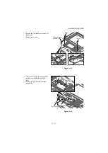
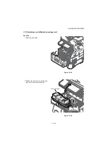
10. Remove two screws.
11. Remove the top tray cover upward.
Figure 1-5-44
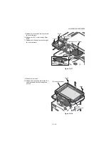
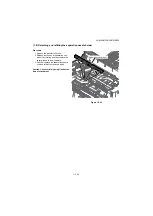
12. Pull the connector and FFC from control
PWB out.
13. Pull the connector and FFC out through
the apertures.
14. Remove four screws and then remove
the laser scanner unit upward.
15. Check or replace the laser scanner unit
and refit all the removed parts.
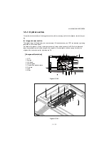
Figure 1-5-45
Screw
Screw
Top tray cover
YC15
YC16
Screw
Screw
Screw
Screw
Apertures
Connector
Control PWB
Laser
scanner unit
FFC
Summary of Contents for P-4030 MFP
Page 7: ...This page is intentionally left blank ...
Page 13: ...This page is intentionally left blank ...
Page 19: ...2NM 2NX 2NY 2NZ 2P0 2P6 5 Installation Guide PF 320 Paper Feeder ...
Page 55: ...2NM 2NX 2NY 2NZ 2P0 2P6 1 2 24 This page is intentionally left blank ...
Page 386: ...2NM 2NX 2NY 2NZ 2P0 2P6 1 5 100 This page is intentionally left blank ...
Page 486: ...Installation Guide PF 320 Paper Feeder Installation Guide ...
Page 487: ...PF 320 㾌㙼 㾌㙼 PF 320 PF 320 PF 320 㪧㪝㪄㪊㪉㪇 㪧㪝㪄㪊㪉㪇䈱 㪧㪝㪄㪊㪉㪇G 㾌 㾌 PF 320 PF 320 ...


