GENISYS II System Hardware Installation
UNION SWITCH & SIGNAL
SM-6900B Rev. 0.0
August 1999
3-9
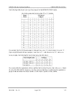
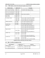
3.2.7 Physical Connections to Serial Ports
SIGNAL
PORT 1
RS-485
PORT 2
RS-485
PORT 3
RS-423
PORT 4
RS-232
TXD-
A2
A16
E16
C20
TXD+
A4
A18
RXD-
C6
A24
E14
C22
RXD+
C8
A26
RTS-
E2
A20
C14
A14
RTS+
E4
A22
CTS-
A10
E12
CTS+
A12
DCD-
C10
A28
E10
C16
DCD+
C12
A30
TXC-
C2
A6
TXC+
C4
RXC-
E6
A8
RXC+
E8
RXREF
E18
COM (0V)
A32
A32
C18
E22
+12V
C24
C24
C24
C24
-12V
C26
C26
C26
C26
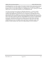
3.2.8 Configuring GENISYS II Serial Ports in the Application Program
All four GENISYS II serial ports have many configuration options. These are made available to
accommodate most requirements that might be encountered in interfacing to modern
communication equipment. Most of the available options are not intended to be used in the
“typical” GENISYS II installation. In most typical installations, only one port configuration
should be used for the GENISYS protocol.
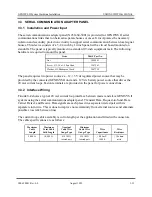
3.2.8.1
Serial Port Configuration for Operation on a Direct Wire, Point-to-Point,
Communication Circuit
GENISYS II serial ports 1, 2, and 3 are designed to operate on a direct wire, multi-drop
communication circuit. When any of these three ports is designated as a GENISYS protocol slave
port, the default port configuration is set by the GENISYS II compiler to accommodate a multi-
drop communication circuit. This causes transmit data (TXD) and request-to-send (RTS) drivers
to assume a high impedance state whenever these ports are not actively placing data on the
communication circuit. This configuration may not be acceptable for most point-to-point
communication circuits. External biasing resistors may be required on inputs to which RTS and
TXD are connected to positively hold those inputs in an unasserted state when RTS and TXD
drivers go to their high impedance state. This problem can be overcome without the use of
external biasing resistors by setting the point-to-point serial port configuration parameter to 1
(POINT.POINT: 1;). This causes RTS and TXD outputs to actively drive the inputs to which
they are connected at all times.
Summary of Contents for GENISYS II
Page 4: ......
Page 6: ...GENISYS II System Hardware Installation UNION SWITCH SIGNAL 1 2 August 1999 SM 6900B Rev 0 0 ...
Page 12: ...UNION SWITCH SIGNAL GENISYS II System Hardware Installation 2 ii August 1999 SM 6900B Rev 0 0 ...
Page 38: ...UNION SWITCH SIGNAL GENISYS II System Hardware Installation 2 26 August 1999 SM 6900B Rev 0 0 ...
Page 40: ...UNION SWITCH SIGNAL GENISYS II System Hardware Installation 3 ii August 1999 SM 6900B Rev 0 0 ...
Page 60: ...UNION SWITCH SIGNAL GENISYS II System Hardware Installation 3 20 August 1999 SM 6900B Rev 0 0 ...
Page 62: ...UNION SWITCH SIGNAL GENISYS II System Hardware Installation 4 ii August 1999 SM 6900B Rev 0 0 ...
Page 66: ...UNION SWITCH SIGNAL GENISYS II System Hardware Installation 4 4 August 1999 SM 6900B Rev 0 0 ...
Page 67: ......


