UNION SWITCH & SIGNAL
GENISYS II System Hardware Installation
3-10
August 1999
SM-6900B Rev. 0.0
Note that for ports designated as master ports, this need not be done. The default configuration of
all master ports is point-to-point. Note also that serial port 4 is capable only of point-to-point
operation regardless of its designated function and the value of the POINT.POINT parameter for
port 4.
3.2.8.2
Basic GENISYS Protocol Serial Port Configuration
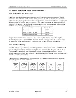
The standard GENISYS protocol configuration is:
STOPBITS:
1
PARITY:
NONE
CARRIER.MODE:
CONSTANT
SECURE.MODE:
ON
(GENISYS MASTER PORT ONLY)
MASTER.CHECKBACK:
OFF
(GENISYS MASTER PORT ONLY)
CRC.SIZE:
16
Some configuration items are intended to vary with the requirements of the installation. The data
rate (BAUD) should be set to accommodate the requirements of the communication system and
system responsiveness. When interconnection of units is accomplished by direct wire, a data rate
of 19200 BPS should be used to ensure good communication response. When modems are used, a
data rate appropriate for the selected modems should be used. This can be determined by
referring to the application information that accompanies the modem being used.
Key-on (KEY.ON.DELAY) and key-off delays (KEY.OFF.DELAY) should be set to 0 for direct
wire connections. For modem connections, key-on and key-off delays should be set to a value
appropriate for the modems being used. This can be determined by referring to the application
information that accompanies the modem. When simple, frequency-shift modems are used (such
as those manufactured by RFL Industries), 8- to 12-bit times is a good value for key-on and key-
off delays. More sophisticated modems and more sophisticated communication links (those with
regenerative repeaters, for example) may require longer key-on and key-off delays. The
approximate required key-on and key-off delays may often be determined empirically by setting
the delays to a high value (about 64-bit times) and attempting to establish communication. Once
communication is established, the delays can be progressively reduced until communication
becomes erratic. About 4- to 8-bit times should be added to the values that produce erratic
operation.
Master port polling timeout (MASTER.TIMEOUT:) must be set to accommodate the worst-case
delay time required for a slave to respond. The default value of 500 milliseconds is usually
adequate. However, when a GENISYS protocol master is communicating with many slaves on a
communication circuit where all slave units may not always be answering, a shorter timeout may
be appropriate to ensure minimum communication delays when slaves occasionally fail to
respond. In any case, the timeout must always be long enough to allow a slave that is capable of
responding sufficient time to respond. This time is approximately equal to twice the worst case
end-to-end delay for the communication channel, plus the worst case communication channel
turnaround delay (relevant only for half-duplex channels), plus the worst case turnaround delay
for a GENISYS II slave port (the time between receiving the last byte of a message and
Summary of Contents for GENISYS II
Page 4: ......
Page 6: ...GENISYS II System Hardware Installation UNION SWITCH SIGNAL 1 2 August 1999 SM 6900B Rev 0 0 ...
Page 12: ...UNION SWITCH SIGNAL GENISYS II System Hardware Installation 2 ii August 1999 SM 6900B Rev 0 0 ...
Page 38: ...UNION SWITCH SIGNAL GENISYS II System Hardware Installation 2 26 August 1999 SM 6900B Rev 0 0 ...
Page 40: ...UNION SWITCH SIGNAL GENISYS II System Hardware Installation 3 ii August 1999 SM 6900B Rev 0 0 ...
Page 60: ...UNION SWITCH SIGNAL GENISYS II System Hardware Installation 3 20 August 1999 SM 6900B Rev 0 0 ...
Page 62: ...UNION SWITCH SIGNAL GENISYS II System Hardware Installation 4 ii August 1999 SM 6900B Rev 0 0 ...
Page 66: ...UNION SWITCH SIGNAL GENISYS II System Hardware Installation 4 4 August 1999 SM 6900B Rev 0 0 ...
Page 67: ......


