UNION SWITCH & SIGNAL
GENISYS II System Hardware Installation
3-6
August 1999
SM-6900B Rev. 0.0
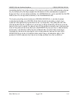
between (-) and (+) conductors of a pair is typically 1.5 to 5 volts, with the (-) conductor negative
with respect to the (+) conductor when the signal is not asserted. (For data lines TXD and RXD,
the quiescent, or unasserted, state is identified as the MARK state.) In addition, the signal
commons (COM) for all ports on an RS-485 communication link must be connected to equalize
potential between signal commons for the connected units. When two GENISYS II units powered
by the same battery are serially connected, the connection of serial commons is made through
negative battery and does not have to be made through the serial cable. Note that COM cannot be
connected to frame or earth ground, as it is directly connected to logic common of the GENISYS
II unit. RS-485 ports should be interconnected using ONLY twisted pair cable with an over-all
shield. For best performance, the interconnecting cables should not contain extra, unused pairs.
Any unused wires should be connected to signal common (COM) at both ends of the cable for
best noise immunity. If connected, the shield should be connected to frame ground at one end of
the cable only. On the units at each end of the communication circuit, 120-ohm, ½ watt external
load resistors should be placed across the TXD and RTS transmitters and across the RXD and
DCD receivers. Any units in-between should simply “bridge” the circuit using a bridging “stub”
that is as short as possible. On a multi-drop communication circuit (a circuit to which more than
two units is connected), the DCD input on the master unit should be biased in its unasserted state.
This may be done by connecting 470-ohm, ½ watt resistors between the DCD- input and 0V and
between the DCD+ input and +5V. The load resistor for the master DCD input should be 240
ohms, ½ watt (rather than 120 ohms) to maintain the required circuit impedance for the biased
circuit. If the CTS input on any serial port is available but not used, it should be forced to its
unasserted state. To permanently force an unused RS-485 input to its unasserted state, the (+)
input should be connected to +5V and the (-) input should be connected to COMMON (0V). To
force an RS-485 input to its asserted state the (+) input should be connected to COMMON (0V)
and the (-) input should be connected to +5V or +12V.
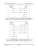
3.2.4 Connecting to RS-423 Serial Ports (Refer to Figure 3-4)
Serial port 3 is the RS-423 serial port: it supports TXD and RTS output signals and RXD, DCD,
and CTS input signals. Data clock signals, including transmit clock (TXC), which may be either
an input or an output, and receive clock (RXC), which is an input, are present but are not
currently supported by the GENISYS II executive. These signals should not be connected. These
signals may be supported in a future release of the GENISYS II executive.
In an RS-423 interface, outputs are referenced to signal common (COM), while inputs have their
own independent common, receive common (RXCOM). Signal outputs are connected to signal
inputs by a single wire as they are in the RS-232 interface, but COM on each end is connected to
RXCOM on the other end. As this connection of commons does not equalize potential between
the signal commons (COM) of the two connected units, an additional connection must be made
between COM terminals on the connected units.
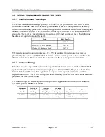
The quiescent or inactive state for all signals is between –3.6 and –6 volts. (For data lines TXD
and RXD, the quiescent state is the MARK state.) The active state for all signals is b3.6
and +6 volts. RS-423 ports should be interconnected using only multi-conductor cable with an
over-all shield. The cable should not contain any twisted pairs. The serial port commons (COM)
should be connected using one of the conductors in the cable (NOT the shield). For best
Summary of Contents for GENISYS II
Page 4: ......
Page 6: ...GENISYS II System Hardware Installation UNION SWITCH SIGNAL 1 2 August 1999 SM 6900B Rev 0 0 ...
Page 12: ...UNION SWITCH SIGNAL GENISYS II System Hardware Installation 2 ii August 1999 SM 6900B Rev 0 0 ...
Page 38: ...UNION SWITCH SIGNAL GENISYS II System Hardware Installation 2 26 August 1999 SM 6900B Rev 0 0 ...
Page 40: ...UNION SWITCH SIGNAL GENISYS II System Hardware Installation 3 ii August 1999 SM 6900B Rev 0 0 ...
Page 60: ...UNION SWITCH SIGNAL GENISYS II System Hardware Installation 3 20 August 1999 SM 6900B Rev 0 0 ...
Page 62: ...UNION SWITCH SIGNAL GENISYS II System Hardware Installation 4 ii August 1999 SM 6900B Rev 0 0 ...
Page 66: ...UNION SWITCH SIGNAL GENISYS II System Hardware Installation 4 4 August 1999 SM 6900B Rev 0 0 ...
Page 67: ......


