4: Operation
4-2
UPS338-01-00 PowerWAVE 8000-RI DPA User Manual Dated 5 April 2013
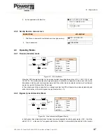
4.2.1 Power Management Display (PMD)
The 2 x 20 character LCD Power Management Display simplifies communication with the UPS and also
provides UPS monitoring information
(See paragraph 4.3)
.
The menu driven LCD enables the access to:
• The ‘Event register’.
• Monitoring the input and output voltage, current, frequency & power.
• Monitoring battery run time.
• Perform commands such as UPS start-up and shut-down, Load transfer from
INVERTER
to
BYPASS
and vice-versa.
• Diagnostic (service mode).
• Adjustments and testing (service mode).
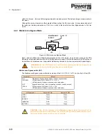
4.2.2 Mimic
LED
indicators
The mimic diagram indicates the status of the general UPS power flow and change colour between Green
and Red (and OFF) to indicate the UPS operating conditions.
LINE 1
(rectifier) and
LINE 2
(bypass) indicate the availability status of the mains power supply.
INVERTER
and
BYPASS
, when green, indicates which of the two sources is supplying the critical load power.
The
BATTERY
LED indicator flashes when the battery is supplying the load – e.g. following a mains failure.
The
ALARM
LED is a visual indication of an internal or external alarm condition. When activated, it is
accompanied by an audible alarm.
LED Indication summary
Operator keys
The operator keys allow the user to:
• Make settings and adjustments via the menu driven LCD display.
• Start-up and shut down the UPS and transfer the load between inverter and bypass.
• Monitor and display the UPS operating voltages, currents, frequencies and other values on the LCD
display.
Indicator
Indicator Status
Interpretation
LINE 1
GREEN
RED
Mains available
Mains not available
LINE 2
GREEN
RED
OFF
Mains bypass OK
Mains bypass not OK or not present
UPS is turned OFF
ALARM
OFF
RED
No alarm condition
Alarm condition (has been reset)
INVERTER
GREEN
RED
OFF
Load on inverter
Inverter fault
Inverter not operating (switched OFF)
BY-PASS
GREEN
OFF
Load on bypass
Bypass not operating (switched OFF)
BATTERY
GREEN
RED
Flashing GREEN
Battery OK
Battery fault or discharged
On Battery
Summary of Contents for PowerWAVE 8000DPA RI
Page 1: ...User Manual PowerWAVE 8000DPA RI Pioneering solutions for total power protection ...
Page 2: ...UPS338 01 00 PowerWAVE 8000 RI DPA User Manual Dated 5 April 2013 ...
Page 4: ...UPS338 01 00 PowerWAVE 8000 RI DPA User Manual Dated 5 April 2013 ...
Page 8: ... iv UPS338 01 00 PowerWAVE 8000 RI DPA User Manual Dated 5 April 2013 ...
Page 10: ...1 Safety 1 2 UPS338 01 00 PowerWAVE 8000 RI DPA User Manual Dated 5 April 2013 ...
Page 16: ...2 General Description 2 6 UPS338 01 00 PowerWAVE 8000 RI DPA User Manual Dated 5 April 2013 ...
Page 42: ...3 Installation 3 26 UPS338 01 00 PowerWAVE 8000 RI DPA User Manual Dated 5 April 2013 ...


