LISA-U2 series - System integration manual
UBX-13001118 - R27
System description
Page 72 of 183
C1-Public
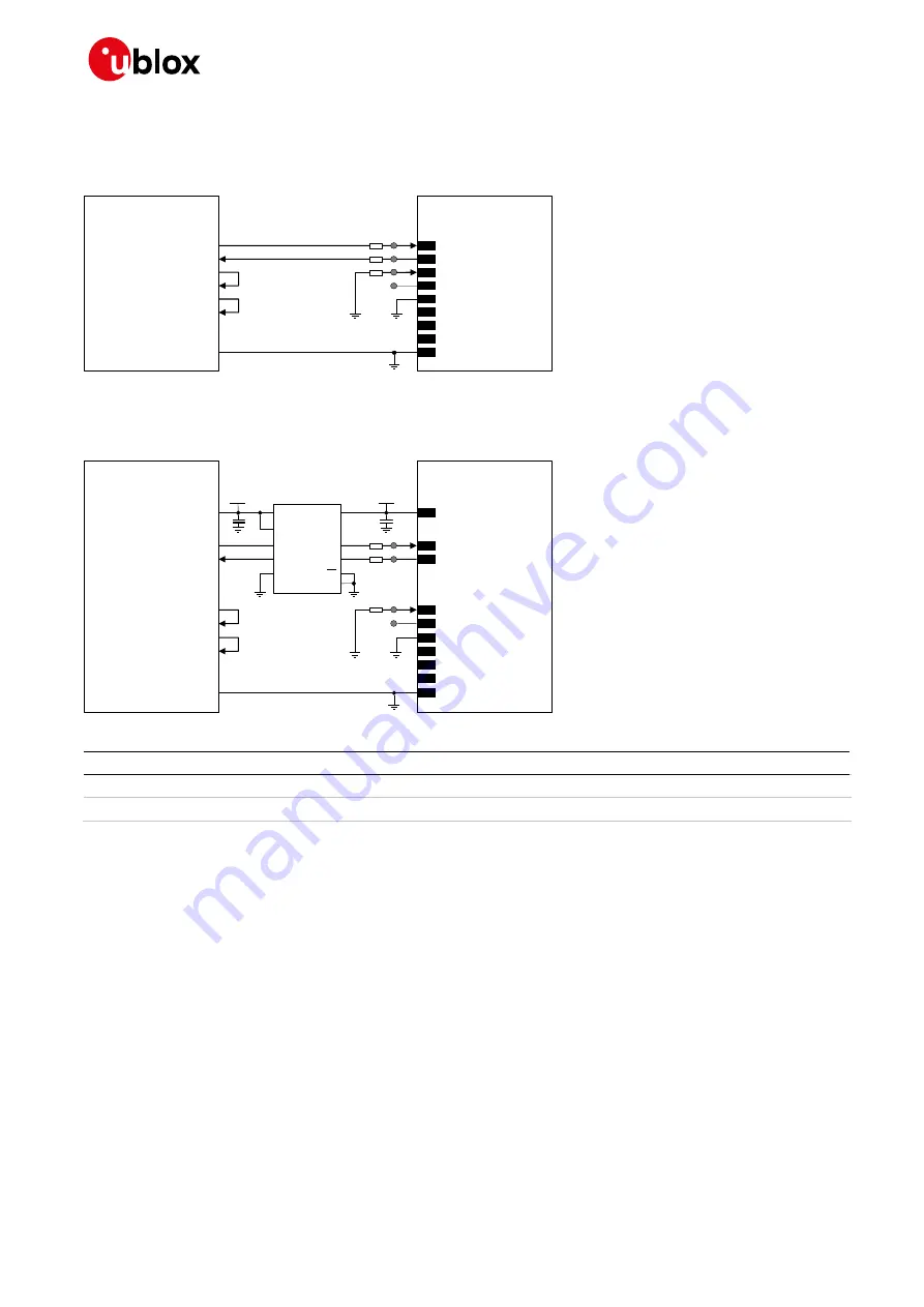
If RS-232 compatible signal levels are needed, the Maxim 13234E voltage level translator can be used.
This chip translates voltage levels from 1.8 V (module side) to the RS-232 standard.
describes the circuit that should be implemented as if a 1.8 V application processor is used.
TxD
Application processor
(1.8V DTE)
RxD
RTS
CTS
DTR
DSR
RI
DCD
GND
LISA-U2 series
(1.8V DCE)
15
TXD
12
DTR
16
RXD
13
RTS
14
CTS
9
DSR
10
RI
11
DCD
GND
0
Ω
0
Ω
TP
TP
0
Ω
TP
TP
Figure 37: UART interface application circuit with partial V.24 link (3-wire) in the DTE/DCE serial communication (1.8V DTE)
If a 3.0 V application processor is used, appropriate unidirectional voltage translators must be
provided using the module
V_INT
output as a 1.8 V supply, as illustrated in
4
V_INT
TxD
Application processor
(3.0V DTE)
RxD
DTR
DSR
RI
DCD
GND
LISA-U2 series
(1.8V DCE)
15
TXD
12
DTR
16
RXD
9
DSR
10
RI
11
DCD
GND
0
Ω
0
Ω
TP
TP
1V8
B1
A1
GND
U1
VCCB
VCC
A
Unidirectional
Voltage Translator
C1
C2
3V0
DIR1
DIR2
OE
VCC
B2
A2
RTS
CTS
13
RTS
14
CTS
0
Ω
TP
TP
Figure 38: UART interface application circuit with partial V.24 link (3-wire) in DTE/DCE serial communication (3.0 V DTE)
Reference
Description
Part Number - Manufacturer
C1, C2
100 nF Capacitor Ceramic X7R 0402 10% 16 V
GRM155R61A104KA01 - Murata
U1
Unidirectional Voltage Translator
SN74AVC2T245 - Texas Instruments
Table 32: Component for UART application circuit with partial V.24 link (3-wire) in DTE/DCE serial communication (3.0 V DTE)
If only the
TxD
and
RxD
lines are provided, as described in
or in
, and HW flow
control is disabled (AT&K0), the power saving must be enabled in this way:
•
AT+UPSV=1: the module automatically enters the low-power idle mode whenever possible and the
UART interface is periodically enabled, as described in section
, reaching low current
consumption.
With this configuration, when the module is in idle mode, the UART is re-enabled 20 ms after the
first data reception, and the recognition of subsequent characters is guaranteed until the module
is in active mode.
☞
If only
TxD
and
RxD
lines are provided, data delivered by the DTE can be lost with these settings:
o
HW flow control enabled in the module (AT&K3, that is the default setting)
o
Module power saving enabled by AT+UPSV=1
o
HW flow control disabled in the DTE
☞
In this case, the first character sent when the module is in idle mode will be a wake-up character
and will not be a valid communication character (see section


